
Generator room ventilation requirements exist to keep a generator set safe, reliable, and ready to start. A properly ventilated room removes engine heat, supplies combustion air, and exhausts harmful gases so the unit can reach full output without overheating or starving for air. Poor ventilation is one of the most common causes of standby generator failure during an outage.
A diesel generator converts only about one-third of its fuel energy into electricity. The rest leaves as heat through the radiator, exhaust, engine block, alternator, and surrounding surfaces. If that heat stays in the room, temperatures rise, air density drops, and the generator loses output. In severe cases, high ambient temperatures trigger thermal shutdowns or accelerate insulation aging.
This guide covers the engineering basics of generator room ventilation design, the code requirements that apply in 2026, a practical CFM calculation, and the field mistakes Huali engineers see most often. For the maintenance side of reliable standby power, see our complete diesel generator maintenance guide. If you need help sizing ventilation for a specific installation, contact Huali’s engineering team.
Key Takeaways
- Generator room ventilation must handle radiator heat rejection, radiant engine heat, and combustion air.
- NFPA 110 Level 1 emergency power supply systems need a minimum room temperature of 40°F (4.5°C) and adequate airflow for full-load operation.
- A quick sizing rule is CFM = (kW rating x 45) + combustion air, assuming a room temperature rise below 20°F.
- Combustion air is roughly 3.5 CFM per kW for diesel generators; always verify with the engine manufacturer.
- Exhaust and intake openings should be on opposite walls to prevent hot-air recirculation.
- Louvers must be sized for net free area, not gross opening, because blades and screens block airflow.
Why Generator Room Ventilation Matters
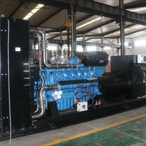
Diesel generator sets produce large amounts of waste heat. A 500 kW unit running at full load can reject more than 1,000 kW of thermal energy into the room and exhaust stream. Without ventilation, that heat accumulates quickly. Room temperature can climb past the generator’s cooling limits within minutes, causing the engine controller to derate or shut down.
High room temperatures also reduce air density. Less dense air means less oxygen per cubic foot, which hurts combustion and increases fuel consumption. The alternator cooling fan works harder, winding temperatures rise, and insulation life drops. Over time, repeated thermal stress leads to premature bearing, gasket, and winding failures.
Beyond heat, ventilation controls toxic gases. Carbon monoxide, nitrogen oxides, and unburned hydrocarbons can leak from exhaust joints, crankcase breathers, and fuel-system vents. A ventilation system that holds the room at a slight negative pressure relative to adjacent spaces keeps fumes from migrating into occupied areas.
Proper ventilation also protects the building. Hot exhaust discharged too close to walls, soffits, or air intakes can damage siding and create re-entrainment loops that feed hot air back into the generator. Code requirements for clearance and discharge height are not suggestions; they are minimum safety margins.
A hospital in Southeast Asia learned this during commissioning. The 1,000 kW standby set started and ran correctly during no-load testing. During the first full-load acceptance test, the radiator discharge duct was too short and blew hot air directly onto the intake louver.
Room temperature climbed 35°F above ambient within 20 minutes. The engine derated and the test failed. Extending the discharge duct and adding a weather hood solved the problem, but the fix delayed project handover by two weeks.
Generator Room Ventilation Requirements and Codes
Several codes and standards govern generator room ventilation. The authority having jurisdiction has the final say, but the following documents form the design baseline.
NFPA 110
NFPA 110, Standard for Emergency and Standby Power Systems, is the primary reference for emergency power supply systems. Key ventilation-related requirements include:
- Level 1 EPSS rooms must maintain a minimum ambient temperature of 40°F (4.5°C) when the generator is not running, so the engine can start and accept load quickly.
- The room ventilation and cooling system must prevent the prime mover from overheating under the highest anticipated ambient temperature at full load.
- The EPS room must be used only for emergency power equipment and direct supporting systems.
- Level 1 installations require a 2-hour fire-rated enclosure when located inside a building.
NFPA 110 does not give a single CFM number. It requires the design to meet the manufacturer’s airflow, temperature, and static-pressure requirements at the installed conditions. That is why the engine data sheet is the starting point for any real calculation.
The standard also ties ventilation to testing. Level 1 systems must start and accept full load within 10 seconds. If the room is too cold, the engine may not reach cranking speed or accept load quickly.
If the room overheats during a monthly loaded exercise or an annual full-load test, the test fails even if the engine is mechanically sound. Ventilation must therefore be verified during loaded testing, not just on paper.
NFPA 37
NFPA 37, Standard for the Installation and Use of Stationary Combustion Engines and Gas Turbines, addresses engine installation clearances and exhaust discharge. Important points include:
- Exhaust outlets must be located to prevent re-entrainment of hot or contaminated gases into building openings or ventilation intakes.
- A common minimum separation is 10 feet (3 meters) from building openings, but local codes may require more.
- Combustible construction must be protected from hot surfaces and exhaust components.
- Adequate combustion and ventilation air must be supplied from outside the room or through properly sized openings.
NEC, IMC, and ASHRAE
- The National Electrical Code (NEC) covers grounding, wiring, and overcurrent protection in generator rooms.
- The International Mechanical Code (IMC) governs mechanical ventilation rates, louvers, ducts, and make-up air for engine rooms.
- ASHRAE publications provide heat-load calculation methods and ventilation design guidance for industrial engine rooms.
Manufacturer Requirements
The most specific requirements come from the generator manufacturer. Engine data sheets list:
- Combustion air flow in CFM or m³/min
- Radiator heat rejection to the room
- Maximum allowable room temperature
- Maximum static pressure across the radiator
- Recommended intake and exhaust louver sizes
Always coordinate the HVAC design with the generator supplier. Generic rules of thumb are useful for budgeting, but the manufacturer’s certified data must govern the final design.
Generator Room Ventilation Design: CFM Calculation
The biggest gap in most generic ventilation articles is the lack of numbers. Here is a practical method MEP engineers use to size generator room ventilation.
The Basic Formula
Total ventilation airflow must remove the heat rejected into the room plus supply the air the engine needs for combustion:
CFM = (Heat rejection to room in Btu/min) / (D x Cp x ΔT) + Combustion air
Where:
- D = air density at room conditions, approximately 0.071 lb/ft³ at 100°F
- Cp = specific heat of air, approximately 0.24 Btu/lb·°F
- ΔT = allowable room temperature rise above outdoor ambient, typically 15–20°F
- Combustion air = air the engine consumes for combustion
For quick estimates at sea level, this simplifies to:
V = (55 x H) / ΔT + Combustion air
Where H is heat rejection to the room in Btu/min.
Quick Rule of Thumb
For generator rooms where combustion air is drawn from the room and the allowable temperature rise is kept below 20°F, a practical rule of thumb is:
Required CFM ≈ (kW rating x 45) + (kW rating x 3.5)
Or simply:
Required CFM ≈ kW rating x 48.5
This captures both cooling and combustion air for typical diesel generators. It is not a substitute for manufacturer data, but it is accurate enough for preliminary layout and louver sizing.
Worked Example: 500 kW Diesel Generator
Consider a 500 kW / 625 kVA standby diesel generator installed in a 30 ft x 20 ft x 12 ft room.
| Design Input | Value |
|---|---|
| Generator rating | 500 kW |
| Engine efficiency | ~38% |
| Heat rejection to room (radiant + alternator) | ~180 kW (estimated from manufacturer data) |
| Allowable temperature rise (ΔT) | 20°F |
| Combustion air rule of thumb | 3.5 CFM/kW |
Step 1: Convert heat rejection to Btu/min
180 kW x 56.9 = 10,242 Btu/min
Step 2: Calculate cooling airflow
CFM = (55 x 10,242) / 20 = 28,166 CFM
Step 3: Add combustion air
Combustion air = 500 x 3.5 = 1,750 CFM
Step 4: Total ventilation requirement
Total CFM = 28,166 + 1,750 = 29,916 CFM, round to 30,000 CFM
This is the air that must move through the room. If the engine draws combustion air through a dedicated duct directly from outside, the room ventilation requirement drops to roughly 28,000 CFM.
Louver Sizing
Louver free area is what matters. A louver with 50% free area only delivers half the airflow of its gross opening at a given face velocity.
At a typical face velocity of 500 FPM (feet per minute):
Net free area = CFM / face velocity = 30,000 / 500 = 60 ft²
With 50% free-area louvers:
Gross louver area = 60 / 0.5 = 120 ft²
For this 500 kW installation, you might use two 8 ft x 8 ft intake louvers and two 8 ft x 8 ft exhaust louvers, depending on the manufacturer’s free-area ratings and pressure-drop data.
Metric Version
For projects using SI units, use the same 500 kW generator example with ΔT = 11°C (equivalent to 20°F).
Step 1: Cooling airflow
Q = (53.5 x 180) / 11 = 876 m³/min
Step 2: Add combustion air
Combustion air = 500 x 0.06 = 30 m³/min
Step 3: Total ventilation
Total Q = 876 + 30 = 906 m³/min, or about 15.1 m³/s
At a typical face velocity of 2.5 m/s, the required net free area is:
Area = 15.1 / 2.5 = 6.0 m²
With 50% free-area louvers, the gross louver area is 12.0 m². This confirms that the imperial and metric approaches produce consistent results when conversions are handled carefully.
The full formula is:
Q (m³/s) = H (kW) / (1.099 x 0.017 x ΔT) + combustion air (m³/s)
Where ΔT is in °C and combustion air is roughly 0.06 m³/s per kW for diesel engines.
Intake, Exhaust, and Airflow Layout
Getting the CFM number right is only half the battle. The air must actually move through the room in a way that cools the generator and does not recirculate hot exhaust.
Intake Location
- Place intake louvers as close as possible to the generator radiator.
- Keep intakes away from exhaust outlets, plumbing vents, and loading docks.
- Size intake openings for the total airflow plus a margin for filter/mesh blockage.
- In dusty or sandy environments, use intake filters with easy access for cleaning.
Exhaust Location
- Place exhaust louvers on the wall opposite the intake to create cross-flow.
- Discharge hot air high on the wall or through the roof to reduce recirculation.
- Maintain NFPA 37 clearances from building openings, combustible materials, and pedestrian areas.
- Avoid discharging exhaust air toward prevailing winds that can blow it back into intakes.
Radiator-Cooled vs. Remote-Cooled
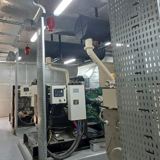
Radiator-cooled generators use a skid-mounted radiator and engine-driven fan. The fan pushes air through the radiator and out of the room. In this arrangement, the room ventilation system mainly removes radiant heat from the engine block, alternator, and exhaust piping.
Remote-cooled generators use a heat exchanger or remote radiator located outside the room. This reduces room airflow requirements but adds a secondary coolant loop, pumps, and controls. Remote cooling is common when the room is too small for the required louvers or when noise constraints limit wall openings.
Static Pressure and Fan Selection
Louvers, screens, ducts, and bends create resistance. The generator radiator fan or supplemental ventilation fans must overcome this static pressure while delivering the required CFM. If the manufacturer specifies a maximum radiator static pressure, the duct and louver design must stay below it. Exceeding the limit reduces cooling airflow and can cause overheating.
When supplemental fans are needed, select them for the total system resistance at the design airflow rate. Use backward-curved or vane-axial fans rated for continuous duty and high temperature. Provide redundancy for Level 1 applications when a single fan failure would overheat the generator.
Types of Generator Room Ventilation Systems
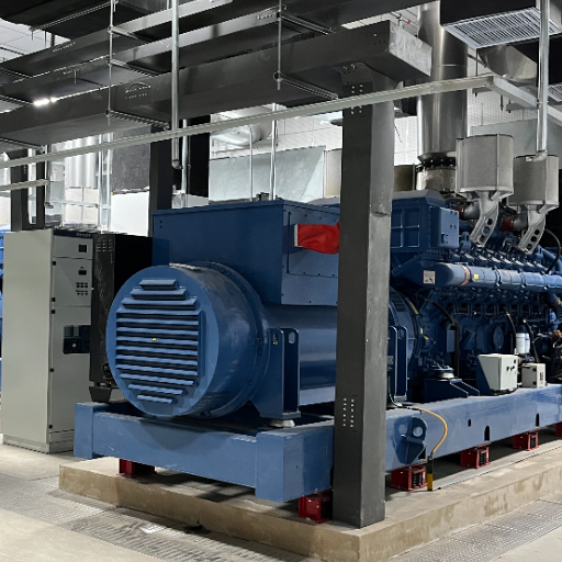
Most installations fall into one of three categories.
Natural Ventilation
Natural ventilation relies on thermal buoyancy and wind pressure. It uses large intake and exhaust openings without powered fans. This approach is simple and has no moving parts, but it only works when:
- The generator is small relative to the room volume.
- The climate is mild.
- The building code allows unpowered ventilation.
- There is enough wall area for oversized louvers.
Natural ventilation is rarely sufficient for diesel standby generators above 200 kW in enclosed buildings.
Mechanical Ventilation
Mechanical ventilation uses intake and exhaust fans to move air. It is the most common approach for commercial and industrial generator rooms because it provides controlled airflow regardless of wind direction or outdoor temperature. Fans can be interlocked with the generator so they start before the engine runs and continue during cool-down.
Radiator-Ducted Ventilation
For radiator-cooled units, the engine-driven radiator fan pulls air through a short duct directly to outside. This is the most efficient arrangement because it uses the engine’s own fan and minimizes room heating. The remaining room ventilation requirement is reduced to radiant and alternator heat only.
Ventilation in Challenging Environments
Standard designs assume sea-level altitude, moderate temperatures, and clean air. Real sites often deviate from all three. Huali ships generator sets to deserts, tropics, coastal areas, and high-altitude mines, so the ventilation design must adapt.
High Altitude
Air density drops roughly 3% for every 1,000 feet of elevation above sea level. At 6,000 feet, the same fan moves about 18% less mass flow. The generator also loses output because the engine breathes less oxygen.
The ventilation system must compensate by increasing CFM, using larger fans, or selecting a derated generator. Always apply altitude correction factors from the manufacturer.
Tropical Climates
High humidity and high ambient temperatures reduce the allowable temperature rise. A generator room in Singapore or Lagos cannot tolerate the same ΔT as a room in London. Increase airflow, use corrosion-resistant louvers, and verify that silencers and ducts drain condensation properly. Insects and mold can quickly clog intake filters, so maintenance intervals must shorten.
Desert and Dusty Sites
Sand and dust are abrasive and insulating. They coat radiators, alternators, and louvers, reducing heat transfer. Use intake filters with automatic pulse-cleaning or washable media where possible.
Position intakes away from vehicle traffic and prevailing dust directions. In extreme cases, provide conditioned air or a sealed remote-cooling arrangement.
Coastal and Corrosive Atmospheres
Salt air accelerates corrosion on aluminum louvers, mild-steel ducts, and radiator cores. Specify marine-grade coatings, stainless-steel hardware, and protective enclosures. Inspect and rinse intake screens regularly to prevent salt buildup.
Noise, Acoustics, and Ventilation Trade-offs
Every opening in a generator room is a path for sound as well as air. Larger louvers improve airflow but increase noise breakout. Acoustic louvers reduce noise but add pressure drop and cost. The design must balance cooling performance with the site’s noise limits.
Common approaches include:
- Acoustic intake and discharge louvers: These use angled baffles lined with sound-absorbing material. They add 0.1–0.3 inches of water column pressure drop, which the fan selection must account for.
- Duct silencers: Inline silencers reduce airborne noise in ducts. They work best when placed close to the generator and require adequate straight duct runs.
Additional options for strict noise limits:
- Barriers and enclosures: Partial walls around the radiator discharge can direct noise away from sensitive areas while preserving airflow.
- Remote cooling: Moving the radiator outside the building reduces the size of room openings and often lowers indoor noise levels.
Huali canopy and containerized sets are built with lined enclosures and engineered air paths. When site noise limits are strict, start with a factory-acoustics package and size ventilation around it rather than adding acoustics as an afterthought.
Common Generator Room Ventilation Mistakes
Huali engineers see the same errors on sites around the world. Avoiding them saves money and prevents failures.
Undersized Louvers
Designers often size louvers by gross opening without accounting for free area. A 4 ft x 4 ft louver with 50% free area only provides 8 ft² of net airflow area, not 16 ft². At 500 FPM, that is 4,000 CFM, not 8,000 CFM.
Recirculation Loops
Exhaust air discharged near an intake or under a soffit gets pulled back into the room. The generator then breathes progressively hotter air until it overheats. Always separate intake and exhaust by at least one building face, and verify discharge direction against prevailing winds.
Ignoring Combustion Air
Some designs only account for radiator cooling and forget that the engine consumes air. A 1,000 kW diesel engine can use 3,500 CFM of combustion air. If the room cannot supply it, the engine loses power and smokes.
Forgetting Maintenance Access
Ventilation grilles, filters, and screens collect dust, leaves, and insects. If they are not accessible for cleaning, airflow drops over time. Design access panels or removable screens at reachable locations.
Tropical and High-Altitude Omissions
At high altitude, air density is lower, so the same CFM carries less cooling capacity. A generator at 2,000 meters may need 20–25% more airflow than at sea level. In tropical climates, high humidity and high ambient temperatures reduce the allowable temperature rise and increase condensation risks in silencers and ducts.
Containerized and Canopy Sets
Containerized generators and sound-attenuated canopies have limited wall area. Ventilation must be designed around the container’s pre-cut openings and the radiator airflow path. Adding a canopy after the generator is selected often forces compromises on louver size and fan selection.
Maintenance Best Practices for Ventilation Systems
A well-designed system will fail if it is not maintained. Add these items to the generator maintenance schedule.
- Inspect intake and exhaust louvers quarterly for debris, bird nests, and corrosion.
- Clean or replace intake filters according to the site dust level.
- Verify fan belts, motors, and controls during monthly generator tests.
For documentation and long-term performance:
- Check that radiator ducts are sealed and not collapsed.
- Measure room temperature during a loaded test at least annually.
- Document airflow obstructions and corrective actions.
For a complete maintenance framework, use our diesel generator maintenance checklist and diesel generator maintenance schedule. For life-safety applications, remember that emergency power generator systems must be tested under load, not just exercised no-load.
Frequently Asked Questions
What are generator room ventilation requirements?
Generator room ventilation requirements are the code and engineering rules that ensure a generator set receives enough fresh air for cooling and combustion while exhaust gases are safely discharged. They cover airflow rates, louver sizing, room temperature limits, clearances, and code compliance with NFPA 110, NFPA 37, NEC, and local mechanical codes.
These requirements are not the same for every installation. A 100 kW residential standby set in a temperate climate needs far less airflow than a 2,000 kW data-center unit in the desert. The final design must start with the engine manufacturer’s data and then adjust for altitude, ambient temperature, dust, noise limits, and local authority interpretations.
How do you calculate CFM for a generator room?
Use the formula CFM = (Heat rejection to room in Btu/min) / (D x Cp x ΔT) + combustion air. For a quick estimate, CFM ≈ kW rating x 48.5 when combustion air is drawn from the room. Always verify the final number against the engine manufacturer’s data sheet.
What is the minimum room temperature for a standby generator?
NFPA 110 requires Level 1 emergency power supply system rooms to be maintained at a minimum of 40°F (4.5°C) when the generator is not running. The manufacturer’s battery and water-jacket heater requirements may specify a higher minimum.
How far must a generator exhaust be from building openings?
NFPA 37 commonly requires exhaust outlets to be at least 10 feet (3 meters) from building openings, air intakes, or combustible construction. Local codes and the authority having jurisdiction may require greater distances.
Can natural ventilation be used for a generator room?
Natural ventilation can work for small generators in mild climates with large wall areas, but most commercial standby installations above 200 kW require mechanical ventilation or radiator-ducted ventilation to meet code and manufacturer requirements.
What is the difference between radiator-cooled and remote-cooled generators?
Radiator-cooled generators have an engine-driven radiator that moves air directly through the room or a duct. Remote-cooled generators use an external heat exchanger or radiator, reducing room airflow requirements but adding pumps, piping, and controls.
How often should generator room ventilation be inspected?
Inspect louvers, filters, and ducts quarterly. Verify fans, motors, and controls during monthly generator tests. Measure room temperature during an annual loaded test.
What happens if a generator room is under-ventilated?
Under-ventilation causes high room temperatures, reduced engine output, poor combustion, increased fuel consumption, and potential thermal shutdown. It can also allow toxic gases to accumulate and damage building finishes.
Generator Room Ventilation Design Checklist
Use this checklist during design review or commissioning:
Design and sizing:
- Obtain the manufacturer’s combustion air, heat rejection, and maximum room temperature data
- Calculate total required CFM for cooling plus combustion air at site altitude and ambient conditions
- Size intake and exhaust louvers for net free area, not gross opening
- Keep intake and exhaust on opposite walls or at least separated by one building face
- Verify NFPA 37 clearances from building openings, combustible surfaces, and pedestrian areas
- Check radiator static pressure against the manufacturer’s limit
Controls and maintenance:
- Coordinate fan control with generator start and cool-down cycles
- Provide intake filtration suitable for the site dust and corrosion environment
- Include room heaters or jacket heaters to maintain 40°F minimum for Level 1 systems
- Test ventilation performance during a loaded run at least annually
- Document airflow measurements, temperature readings, and corrective actions
Conclusion
Generator room ventilation requirements are not optional details. They determine whether a standby generator can start reliably, run at full load, and survive its design life. The design process starts with the manufacturer’s data, adds the heat-rejection and combustion-air calculations, sizes louvers for net free area, and lays out intake and exhaust to prevent recirculation.
Codes such as NFPA 110 and NFPA 37 set the minimum safety baseline, but the final design must also account for altitude, climate, dust, and the specific generator configuration. A 500 kW diesel generator can need 30,000 CFM of ventilation air. Missing that number by half is a common and expensive mistake.
Getting the design right before construction starts avoids change orders, failed acceptance tests, and thermal shutdowns in service. Invest time in the airflow calculation, louver sizing, and site-specific adjustments. The result is a generator room that protects the equipment, the building, and the people who depend on backup power.
Shandong Huali Electromechanical supports diesel generator room ventilation design for sets from 8 kVA to 4,000 kVA, including open-set, canopy, and containerized installations. Every Huali generator leaves the factory with rated-load testing, and our engineering team can review room layouts, airflow paths, and louver sizing before equipment ships. Contact our engineering team for ventilation sizing, layout review, or a complete standby power proposal.
