A complete diesel generator installation guide follows five phases: site planning, civil works, mechanical and electrical hookup, automatic transfer switch (ATS) wiring, and NFPA 110 commissioning. Skip any of them and the generator that cost you six figures will fail when it matters most.
Industry data shows more than 30% of new generator commissioning failures trace back to installation shortcuts, not equipment defects. Galvanized fuel lines that flake into injectors. Concrete pads pouring cracks within a year. ATS units that transfer but never sync back. A weekend of saved labor becomes a six-figure outage twelve months later.
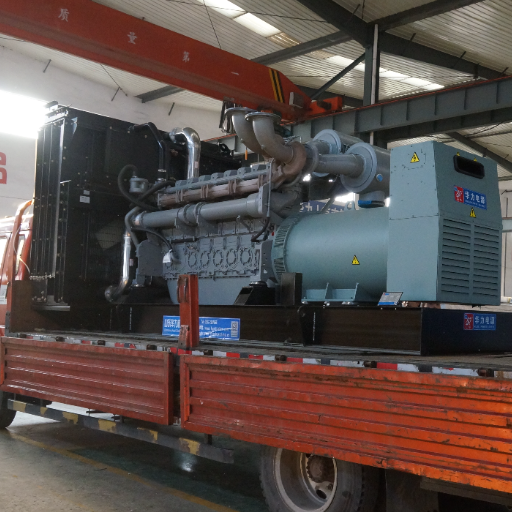
At Shandong Huali Electromechanical Co., Ltd., we manufacture and ship diesel generator sets from 8 kVA to 4,000 kVA to more than 20 countries. After 25 years, we have seen the same installation mistakes repeat on five continents. This guide consolidates the workflow our engineers walk every distributor and EPC partner through, with the codes, specifications, and decisions that actually matter. For broader buyer guidance, see our companion piece on how to choose a diesel generator.
Key Takeaways
- A code-compliant diesel generator installation is a five-phase project: planning, civil, mechanical/electrical, ATS, and commissioning.
- Concrete pads should be at least 6 inches thick, 2,500 psi minimum, with reinforced mesh, and extend 6 inches past the genset footprint.
- Open-transition ATS units cost 30 to 50% less than closed-transition; choose closed-transition for hospitals, data centers, and any Level 1 emergency system.
- NFPA 110 acceptance requires a 2-hour full-load step test plus a cold start, witnessed by the Authority Having Jurisdiction (AHJ).
- Skipping load bank testing is the single most expensive shortcut in commissioning; it can mask defects that cost 10 to 100 times more to fix during a real outage.
The Complete Diesel Generator Installation Guide Workflow
A diesel generator installation is a project, not an event. For industrial gensets above 100 kVA, expect 6 to 12 weeks from purchase order to “Auto” mode.
The five phases run in sequence:
- Planning & Permitting (1 to 3 weeks). Load study, single-line drawing, permit submittal, AHJ pre-application meeting.
- Civil Works (1 to 2 weeks). Concrete pad, conduit stub-ups, fuel containment, exhaust penetrations.
- Mechanical & Electrical Installation (2 to 4 weeks). Genset set, fuel piping, exhaust, primary cables, battery, controls.
- ATS Installation & Tie-In (1 to 2 weeks). Mount ATS, wire line/load/generator/control circuits, utility coordination.
- Commissioning (1 to 2 weeks). First start, phase rotation, NFPA 110 step load test, cold start, documentation handover.
Four parties own different parts of the project. The installing contractor is responsible for civil and electrical installation and pre-commissioning punch list. The OEM factory representative configures controls, sets protection, performs first start, and activates the warranty clock. The owner’s representative witnesses tests, accepts handover, and ensures the operations team is trained. The Authority Having Jurisdiction (AHJ) witnesses the NFPA 110 acceptance test and signs off for occupancy. For complex paralleling plants and 2N data center topologies, add a controls integrator and an independent third-party testing firm.
Site Preparation: Foundation, Clearances, and Ventilation
Site preparation is the most under-budgeted phase of any diesel generator installation guide. The pad, the clearances, and the airflow design dictate every reliability outcome that follows.
Concrete Pad Specifications
The generator pad foundation requirements vary with engine size, but the pad must always support the wet weight of the genset plus dynamic loads from engine vibration. For most industrial diesel units:
- Minimum thickness: 6 inches for units under 500 kW; 8 to 12 inches above 500 kW
- Concrete strength: 2,500 psi at 28-day cure (some AHJs require 3,000 psi)
- Reinforcement: #4 rebar on 12-inch centers, or 6×6 W2.9/W2.9 welded wire mesh
- Pad extension: At least 6 inches past the genset footprint on all sides
- Slope: 1/8 inch per foot away from the building or fuel tank to manage rainwater
- Vibration isolation: Spring or rubber isolators rated for the genset’s vibration profile, never bolt the unit hard to concrete
In seismic zones, anchor designs must reference local code (IBC, Eurocode 8, or regional equivalent). For coastal sites, specify epoxy-coated rebar to resist chloride attack.
Clearances and Setbacks
NFPA 37 sets minimum separations between stationary combustion engines and combustible structures. Standard practice:
| Clearance | Minimum | Typical Specification |
|---|---|---|
| Genset to building (combustible wall) | 5 ft | 10 ft for service access |
| Genset to property line | Per AHJ | 10 to 25 ft |
| Genset to operable openings (doors, windows) | 5 ft | 10 ft |
| Fuel tank to ignition source | 5 ft | Per NFPA 30/37 |
| Service clearance front | 3 ft | 4 to 6 ft for radiator pull |
| Service clearance sides | 3 ft | 3 ft minimum |
Indoor installations require additional fire-rated enclosure construction, typically a 2-hour rated room per NFPA 110.
Ventilation and Cooling Air
A 1,000 kW diesel genset can move 30,000 cubic feet per minute (CFM) of cooling air. Outdoor enclosed units handle this themselves. Indoor installations need engineered intake louvers and discharge ductwork.
Practical guidelines:
- Intake louver area: At least 1.5 times the radiator face area
- Discharge ducting: Sized for less than 0.5 inches water gauge backpressure
- Motorized dampers: Open on engine start, fail open on power loss
- Sound attenuation: Add silencers if site noise limits apply, or specify a silent diesel generator enclosure rated for your site’s dBA limit
Need a generator pre-engineered for tight indoor or rooftop installation? We design custom diesel generator sets and containerized generator packages with integrated silencers, pre-routed cable entries, and factory-mounted ATS provisions to simplify site work.
Fuel System & Exhaust Installation
Fuel and exhaust are where shortcut culture causes the most warranty claims. Two materials and one slope rule prevent most of the failures we see in the field.
Fuel Tanks: Day Tank vs. Sub-Base
Most industrial diesel gensets use one of two fuel storage configurations:
- Sub-base tank: A double-wall steel tank that doubles as the genset skid base. Capacities from 24 hours up to 96 hours of runtime. The simplest layout, but limited in capacity.
- Day tank with bulk storage: A small tank near the engine fed from a larger remote bulk tank. Required for runtime above what a sub-base can hold or where bulk storage must sit away from the engine.
NFPA 110 requires Level 1 emergency systems to carry enough on-site fuel for the system’s “Class” designation, typically 4, 8, 24, 48, or 96 hours. To right-size tank capacity by load profile, see our guide on diesel generator fuel consumption.
Fuel Lines: Materials Matter
Never use galvanized piping for diesel fuel. Diesel reacts with zinc coating, releasing flakes that clog filters and damage injectors. Acceptable materials:
- Black iron pipe with welded or threaded joints (Schedule 40 minimum)
- Stainless steel
- UL-listed flexible diesel hose for vibration isolation joints near the engine
Always include a flexible section at the engine connection to absorb vibration. Slope supply lines back toward the tank at 1/4 inch per foot to drain on shutdown.
Vent Lines and Containment
Tank vent terminations must end at least 12 feet above grade and 5 feet from any building opening per NFPA 30. Spill containment under the tank must hold 110% of the tank’s volume. Outdoor sub-base tanks are double-wall by design and require leak monitoring per the AHJ.
Exhaust Routing
Exhaust gas exits the engine at 850 to 1,200°F. Heat shielding, expansion joints, and condensate drains are non-negotiable.
- Exhaust pipe slope: Downward at 1/4 inch per foot from the engine, with a drain leg before any vertical rise
- Heat shielding: Insulated or jacketed pipe within 18 inches of combustibles
- Rain cap or curved stack: Required to prevent water ingress
- Backpressure limit: Below the engine manufacturer’s spec, typically 27 to 40 inches water column
Cable Sizing and Electrical Connections
Power cables between the generator and the ATS or main distribution board carry the full output current. Undersized cables overheat, voltage drops, and breakers nuisance-trip.
Sizing the Generator Output Cable
Cable size depends on full-load amps, run length, voltage drop tolerance, ambient temperature, and conduit fill. A 500 kW genset at 480V, 0.8 PF draws approximately 753 amps full load. NEC ampacity tables call for 600 kcmil copper or parallel 350 kcmil runs at 75°C insulation.
Rule of thumb for run length: keep voltage drop under 2% from genset to ATS, and another 2% from ATS to load.
Conduit, Grounding, and Neutral Bonding
- Conduit: Rigid galvanized steel (RGS) or EMT depending on environment. Use liquid-tight flex for the last 18 inches to the genset to absorb vibration.
- Grounding: A dedicated ground rod at the genset connected by minimum #6 AWG copper. Bond to building ground at the service entrance, never twice.
- Neutral bonding: This is the single most common installation error we see. The neutral can be bonded only at one point in the system, either at the service entrance, at the generator, or at the ATS, depending on configuration. Double bonding causes circulating currents and false ground faults.
Control Wiring
Beyond the main power cables, the genset requires:
- 2-wire start circuit to the ATS, typically 14 to 16 AWG
- Position-indication wiring between ATS and genset control
- Battery charger circuit: Minimum 5A 120V (or 230V)
- Block heater circuit: Sized per engine spec, typically 15 to 30A
- RS-485 communications (Modbus or BACnet) if the genset is monitored by a BMS
Use Belden #9460 or equivalent shielded twisted pair for all serial communication runs.
Automatic Transfer Switch (ATS): Open Transition vs Closed Transition ATS Selection
The automatic transfer switch installation is what turns a generator from a standalone asset into an emergency power system. Choose the wrong ATS type and you either burn money on capability you do not need or, worse, accept transition behavior your loads cannot survive. The first decision is open transition vs closed transition ATS, and the answer depends almost entirely on what loads sit downstream.
Open Transition ATS (Break-Before-Make)
An open-transition ATS opens the utility connection before closing the generator connection. There is a brief power interruption, typically 100 to 500 milliseconds.
- Best for: Lighting, HVAC, general motor loads, most commercial buildings
- Cost: Baseline
- Limitation: The momentary interruption restarts electronics, drops UPS to battery, and trips sensitive process equipment
A subtype called in-phase transition waits until utility and generator are in phase before transferring, reducing motor inrush. Transition window typically below 150 ms.
Closed Transition ATS (Make-Before-Break)
A closed-transition ATS briefly parallels the utility and generator (typically less than 100 milliseconds) before opening the source being disconnected. Loads see no interruption.
- Best for: Hospitals, data centers, broadcast facilities, any Level 1 emergency system under NFPA 110
- Cost: 30 to 50% premium over open transition
- Requirement: Utility approval is mandatory because the genset briefly synchronizes with the grid
Delayed Transition ATS
A delayed-transition ATS pauses in a neutral position for 1 to 30 seconds between sources. This lets large motors coast down before re-energizing on the new source.
- Best for: Heavy motor loads, chillers, elevators, pumps that experience destructive re-energization torque
- Tradeoff: Brief total power loss during the neutral dwell
ATS Decision Matrix
| Load Type | Recommended Transition |
|---|---|
| Hospital life-safety branch | Closed transition + bypass isolation |
| Data center IT load (with UPS) | Closed transition |
| Data center mechanical (chillers) | Delayed or closed transition |
| Office lighting & HVAC | Open transition |
| Industrial motor loads | Delayed transition |
| Elevator power | Open or delayed transition |
| Broadcast / studio | Closed transition |
| Light commercial standby | Open transition |
Erbil hospital project (Iraq). A regional EPC contractor specified an open-transition ATS for a Level 1 hospital emergency system to save on initial cost. During the Joint Commission audit, the auditor flagged the configuration as non-compliant with closed-transition expectations for life-safety branches. The hospital retrofitted to a closed-transition ATS with bypass isolation at roughly three times the original equipment cost, plus a 6-week schedule delay. The savings on the original purchase order became a $180,000 lesson on choosing transition type by code, not by budget.
How to Install an Automatic Transfer Switch: Sizing and Wiring
Once you choose the transition type, the automatic transfer switch installation itself comes down to four decisions: amperage, location, terminal wiring, and control circuits. The same approach applies whether you are specifying a 200 A ATS for a small commercial site or a 3,200 A ATS for a hospital service entrance.
ATS Amperage Sizing
ATS continuous current rating must equal or exceed the largest of:
- The generator’s full-load current
- The service entrance rating (if the ATS is service-rated)
- The downstream panel main breaker
Common pairings:
| Generator Size (480V, 0.8 PF) | Full-Load Amps | Typical ATS Rating |
|---|---|---|
| 100 kW | 150 A | 200 A |
| 250 kW | 376 A | 400 A |
| 500 kW | 753 A | 800 A |
| 750 kW | 1,128 A | 1,200 A |
| 1,000 kW | 1,503 A | 1,600 A |
| 1,500 kW | 2,255 A | 2,500 A |
| 2,000 kW | 3,007 A | 3,200 A |
For Saudi Arabia, the Philippines, and other 60Hz countries, confirm voltage compatibility. See our guide on 50Hz vs 60Hz generator selection before specifying the ATS.
Service Entrance vs. Downstream
A service-entrance ATS sits at the main service location and acts as the service disconnect. It must include a neutral disconnect for system grounding to work properly. A downstream ATS sits between a main panel and a critical load subpanel, leaving the utility service disconnect upstream.
For most data centers and hospitals, a service-entrance ATS with bypass-isolation is standard. Bypass isolation lets you service the ATS while the load stays powered, a critical feature for 24/7 facilities. For 2N and N+1 topologies, see our deep dive on data center generators for paralleling and redundancy design.
Terminal Wiring: Line, Load, Generator, Control
A standard ATS has four sets of conductors:
- Line (Source 1): Utility incoming power
- Generator (Source 2): From the genset output breaker
- Load: To downstream distribution
- Control: Two-wire start signal back to the genset, position indication, exercise clock
Confirm lug sizing before installation. ATS lug compatibility with cable gauge is one of the top three field issues, often resolved by parallel cable runs or special lug kits from the OEM.
Two-Wire Start Circuit
The classic two-wire start circuit for an ATS for generator control is a normally-open dry contact at the ATS that closes when utility power fails. The genset’s controller sees the closed contact and starts the engine. When utility returns, the contact opens, the controller starts a cooldown timer, and the engine stops.
Keep this circuit on its own conductor pair, separated from power cables. Belden #9460 or equivalent shielded twisted pair prevents nuisance starts from induced voltage on adjacent power runs.
Want a complete factory-built genset and ATS package? We supply Cummins-powered diesel generator sets with ATS units pre-wired and factory-tested as a matched system, reducing field commissioning time by up to 40%.
Commissioning, Load Bank Testing & NFPA 110 Acceptance
Commissioning is where you prove the installation works. The generator commissioning checklist is the difference between a system you can trust and one that fails on its first real call.
Pre-Start Inspection
Before the engine cranks the first time, verify:
- Engine oil and coolant at full marks
- Battery charged, terminals torqued, electrolyte level correct
- Fuel tank between 30% and 95% full, lines bled
- All breakers in the correct position
- ATS in “Off” or test mode
- Work area clear of debris, tools removed from genset enclosure
First Start and Controls Configuration
The OEM factory representative typically performs the first start. They verify oil pressure, coolant flow, exhaust pattern, and AVR response. They program the engine controller’s protection setpoints, exercise schedule, and ATS communication. Phase rotation must be confirmed before any load is connected; a reversed phase will spin three-phase motors backwards on transfer.
NFPA 110 Step Load Test
The core of acceptance testing is the NFPA 110 acceptance test: a 2-hour full-load step test. Building load combined with a portable load bank brings the genset to 100% of nameplate kW (less site derating). The test is witnessed by the AHJ and documented per NFPA 110 Chapter 7.
The step load sequence typically follows manufacturer guidance, applying load in 25% increments while recording voltage, frequency, fuel pressure, oil pressure, and coolant temperature at each step. After two hours at full load, the load is removed in reverse sequence and the engine continues for a 5-minute cooldown.
Cold Start Test
NFPA 110 paragraph 8.4.4 requires the EPS to start and accept full load without manual pre-warming. The system must hit rated voltage and frequency within the time window for its Type designation: 10 seconds for Type 10 (the most common emergency power requirement).
Documentation Handover (Close-Out Package)
A complete close-out package includes:
- As-built drawings (single-line, control schematics)
- Permits and AHJ sign-off
- Manufacturer warranty registration
- NFPA 110 acceptance test report
- Load bank test data
- O&M manuals and spare parts list
- Training records for the owner’s operations team
For ongoing reliability after commissioning, follow a structured diesel generator maintenance schedule from day one.
Manila data center incident. A colocation operator pushed go-live to meet a tenant deadline and asked the commissioning team to skip the 2-hour load bank test. Eight months later, during a typhoon-driven utility outage, the genset started, transferred, then shut down on a stuck fuel solenoid that a load test would have caught. The 4-hour outage triggered SLA penalties estimated at 220,000.Theskippedloadbanktestwouldhavecostroughly220,000.Theskippedloadbanktestwouldhavecostroughly5,000. The math on commissioning is always lopsided in favor of doing the work.
Common Generator Installation Mistakes to Avoid
After two and a half decades of factory and field experience, the failure modes repeat. These are the seven mistakes that drive the most warranty claims and unplanned outages:
- Galvanized fuel piping. Zinc reacts with diesel and produces flakes that destroy injectors. Use black iron, stainless, or UL-listed flexible diesel hose only.
- Missing or undersized vibration isolators. Hard-bolted gensets crack concrete pads and shorten alternator bearing life. One Mombasa cement plant lost a 1,200 kVA Weichai alternator at 800 hours after isolators were omitted, costing $48,000 in unplanned rebuild plus nine days of plant downtime.
- Double neutral bonding. Bonding the neutral at both the service entrance and the generator creates circulating ground currents and false trips. Bond at one point only.
- Undersized ATS. Specifying an ATS rated for nameplate amps with no margin leaves no headroom for downstream growth. Round up to the next standard rating.
- Wrong exhaust slope. Exhaust must slope away from the engine to drain condensate. Reverse slope sends water and acidic condensate back into the turbo.
- Weak foundation. Cracking concrete pads within the first year almost always trace to skipped rebar, low concrete strength, or missing pad extension.
- Skipped load bank test. The cheapest moment in the lifecycle to catch a hidden defect. Skipping it converts a $5,000 routine test into a six-figure outage event.
Frequently Asked Questions
What is included in a diesel generator installation?
A complete diesel generator installation includes site planning and permits, a reinforced concrete pad, the genset itself with vibration isolation, fuel system (sub-base or day tank with bulk storage), exhaust routing with heat shielding, primary power cables and conduit, grounding and neutral bonding, an automatic transfer switch wired with line/load/generator/control circuits, controls integration, and full NFPA 110 acceptance testing including a 2-hour load bank step test.
How is an ATS installed?
An ATS is mounted near the main distribution board, typically wall-mounted or floor-standing depending on amperage. The installer wires the line conductors from utility, the generator conductors from the genset breaker, the load conductors to the downstream panel, and the control circuits including the two-wire start signal back to the genset. The OEM representative configures transition settings, exercise schedule, and protection setpoints during commissioning.
What is the difference between open and closed transition ATS?
An open-transition ATS opens the source being disconnected before closing the new source, creating a brief power interruption of 100 to 500 milliseconds. A closed-transition ATS briefly parallels both sources (less than 100 milliseconds) so loads see no interruption. Closed transition costs 30 to 50% more and requires utility approval, but is essential for hospitals, data centers, and any NFPA 110 Level 1 emergency system.
How do I size an automatic transfer switch?
Size the ATS continuous current rating to equal or exceed the largest of three values: the generator’s full-load amperage, the service entrance rating if the ATS is service-rated, or the downstream panel main breaker rating. For a 500 kW generator at 480V three-phase, full-load amps are approximately 753, so an 800-amp ATS is the correct standard size.
How long does a generator installation take?
For an industrial diesel generator above 100 kVA, expect 6 to 12 weeks from purchase order to “Auto” mode. Planning and permits take 1 to 3 weeks, civil works 1 to 2 weeks, mechanical and electrical installation 2 to 4 weeks, ATS installation 1 to 2 weeks, and commissioning 1 to 2 weeks. Complex paralleling or data center installations can take 16 to 24 weeks.
What is NFPA 110 acceptance testing?
NFPA 110 acceptance testing is the on-site validation required before a new emergency power supply system is placed in service. It includes a 2-hour full-load step test using building load supplemented by a portable load bank, a cold start test confirming the engine reaches rated voltage and frequency within the Type-designated time window, and witnessed verification by the Authority Having Jurisdiction.
Do I need a permit for generator installation?
Yes. Most jurisdictions require an electrical permit, a mechanical permit, and often an environmental permit for fuel storage. Permit fees typically run 150to150to600 and processing takes 2 to 4 weeks. Indoor installations require additional fire-rated room construction permits. Always hold a pre-application meeting with the AHJ to confirm requirements before submittal.
Can I install a generator myself?
For residential standby units under 22 kW, some jurisdictions allow homeowner installation, but a licensed electrician must perform the ATS and service tie-in. For any commercial or industrial diesel generator, installation must be performed by licensed electrical and mechanical contractors, and commissioning requires the OEM factory representative for warranty activation. Self-installation voids most manufacturer warranties.
Conclusion
A successful diesel generator installation guide comes down to discipline across five phases: planning and permitting, civil works, mechanical and electrical installation, ATS wiring, and NFPA 110 commissioning. Each phase has a small number of decisions that determine reliability for the next 20 years. Skip the rebar, you lose the pad. Skip the closed-transition ATS, you lose your code compliance. Skip the load bank test, you lose the first real outage.
For exporters and EPC partners, the most valuable practice is treating the generator and the ATS as a matched system, not two separate purchases. Factory-tested packages reduce field commissioning time and eliminate the integration surprises that drive most schedule slips.
At Shandong Huali Electromechanical Co., Ltd., we manufacture diesel generator sets from 8 kVA to 4,000 kVA paired with matched ATS configurations in open, closed, delayed, and bypass-isolation variants. Every unit is tested at our national standard testing center before shipment, and our engineering team supports installation contractors with single-line drawings, cable sizing, and commissioning checklists in 20+ countries.