
To calculate generator room ventilation, add three air flows: combustion air at roughly 5-7 m³/h per kW, radiator cooling air at 30-50 m³/h per kW that must be ducted straight outside, and room heat-removal air at 15-25 m³/h per kW. The total usually lands between 50 and 80 m³/h per kW, sized to keep the room no more than 10 °C above ambient at full load.
Here’s the trap most design guides skip. The radiator fan is already the biggest fan in the room. What it needs is an unobstructed path, and the rooms that overheat are usually the ones where someone added more fans instead of clearing that path.
You don’t need a wind-tunnel engineer to get this right. This guide walks through the three flows, the heat-balance formula, a full worked example for a 500 kW set, the louver and fan sizes that come out of it, and the NFPA 110 rules that make the design enforceable.
Key Takeaways
- Generator room ventilation has three jobs: combustion air, radiator cooling air, and room heat removal. A typical design totals 50-80 m³/h per kW.
- Size the airflow to keep the room no more than about 10 °C above ambient at full load; above roughly 40-45 °C the set starts derating.
- The accurate method is a heat balance: airflow = heat to room ÷ (ρ × Cp × ΔT). For a 500 kW set, that works out to about 35,000 m³/h of total intake.
- Intake louvers need about 1.5 times the radiator face area (2 times in hot climates), sized on net free area, with the exhaust outlet on the opposite wall.
- NFPA 110 requires motorized louvers that fail open, ventilation fans on emergency power, and ventilation alarms on the remote annunciator.
Why a Generator Room Needs Ventilation at All
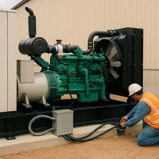
A diesel generator rejects heat in three directions: through the radiator, through the exhaust pipe, and straight off the engine block and alternator. If the room cannot get rid of the last two, the set heats its own intake air, and a diesel engine loses power as its intake temperature climbs.
Ventilation does two more jobs at the same time. It feeds the engine its combustion air, and it dilutes fumes and carbon monoxide that collect in a confined space. Three jobs, three different air flows.
The overview of the whole topic, including room layout and clearances, lives on our generator room ventilation guide. This article is the calculation that the guide does not show.
If any of the three flows is short, the symptoms show up first in summer. An undersized room vents the set derating on the hottest day, then tripping on high coolant temperature.
The Three Air Flows in Every Generator Room Ventilation Calculation
Each flow has its own per-kilowatt rate, and each rate answers a different physical requirement.
| Air flow | Typical rate | What it does |
|---|---|---|
| Combustion air | 5-7 m³/h per kW | Feeds the engine; drawn in from the room |
| Radiator cooling air | 30-50 m³/h per kW | Cools the jacket water; ducted straight outside |
| Room heat-removal air | 15-25 m³/h per kW | Removes block, alternator, and exhaust radiation |
| Total intake | 50-80 m³/h per kW | Everything the intake opening must admit |
Using mid-range values, a set’s total intake airflow scales like this:
| Set size | Combustion air | Radiator air | Room air | Total intake |
|---|---|---|---|---|
| 50 kW | 300 m³/h | 2,000 m³/h | 1,000 m³/h | 3,300 m³/h |
| 100 kW | 600 m³/h | 4,000 m³/h | 2,000 m³/h | 6,600 m³/h |
| 250 kW | 1,500 m³/h | 10,000 m³/h | 5,000 m³/h | 16,500 m³/h |
| 500 kW | 3,000 m³/h | 20,000 m³/h | 12,000 m³/h | 35,000 m³/h |
| 1,000 kW | 6,000 m³/h | 40,000 m³/h | 24,000 m³/h | 70,000 m³/h |
These are planning numbers, not gospel. The set’s specification sheet gives the real radiator airflow and heat rejection, and that data wins every time. The Cummins application manual makes the same point: use the published set data and the louver manufacturer’s restriction charts, and treat rules of thumb as a cross-check.
If you are mid-design and want these numbers checked against your actual set, our engineers run this calculation for every indoor and containerized installation we quote.
The Heat-Balance Calculation (the Accurate Method)
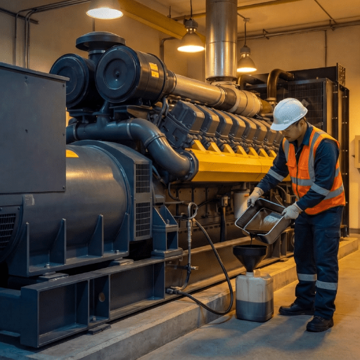
The clean way to size the room-ventilation portion is a heat balance:
Q = (heat to room × 1000) ÷ (ρ × Cp × ΔT)
Here, Q is the airflow in m³/s and heat to the room is in kilowatts. Air density ρ is about 1.2 kg/m³, Cp is the specific heat of air at about 1.005 kJ/(kg·K), and ΔT is the temperature rise you will accept, usually 10-15 °C.
The heat that reaches the room comes from three places. The alternator sheds 2-5 percent of its rating in winding and core losses. The engine block and the exhaust pipe radiate heat continuously at full load. And the radiator rejects the largest share of all, which is exactly why that flow must leave the room directly instead of heating it.
A useful starting figure for an air-cooled indoor set: roughly 6-8 percent of the rated output ends up as heat dumped into the room. For a 500 kW set, that is about 35-40 kW, and that number drives the whole calculation.
In a water-cooled installation with a remote radiator or heat exchanger, the job changes. There is no big radiator airflow to handle, so ventilation is sized to dilute harmful gases instead, typically holding carbon monoxide under about 30 mg/m³ or providing at least 20 m³/(kW·h) of intake air.
Yusuf, a facility engineer in Dubai, commissioned an 800 kW set in a plant room where the installer had run the radiator discharge through a short duct that stopped three feet short of the wall. On a 45 °C August afternoon, hot air looped straight back into the intake. The room climbed past 52 °C, the set derated by roughly 15 percent, and the high water-temperature alarm tripped three times a week. The fix cost a canvas connector, a straight-through duct to the wall louver, and an exhaust opening moved to the opposite side. Same set, same ambient temperature, 41 °C room, no more alarms.
How to Calculate Generator Room Ventilation: Worked 500 kW Example
Here is the full chain for one set, so you can see the arithmetic from heat rejection to louver size.
| Step | Calculation | 500 kW result |
|---|---|---|
| 1. Heat to room temperature | About 8% of the rating (alternator, block, exhaust) | ≈ 40 kW |
| 2. Heat-removal airflow | 40,000 ÷ (1.2 × 1005 × 10) | ≈ 12,000 m³/h |
| 3. Combustion air | About 6 m³/h per kW | ≈ 3,000 m³/h |
| 4. Radiator cooling air | From the set specification sheet | ≈ 20,000 m³/h |
| 5. Total intake airflow | Steps 2 + 3 + 4 | ≈ 35,000 m³/h |
| 6. Intake louver net free area | Airflow ÷ face velocity (max 3 m/s) | ≈ 3.2 m² |
| 7. Exhaust discharge | Intake minus combustion air | ≈ 32,000 m³/h |
| 8. Mechanical exhaust fan | Room airflow plus 10-15% margin | ≈ 14,000 m³/h |
| 9. Air changes per hour | Room airflow ÷ room volume | ≈ 25 ACH in a 600 m³ room |
Two things stand out in this table. First, the radiator airflow is bigger than the other two flows combined. Getting it ducted straight outside matters more than adding another exhaust fan. Second, the mechanical fan only has to handle the room-ventilation portion, about 14,000 m³/h with margin for a 500 kW set. The radiator fan already moves 20,000 m³/h itself.
The air-change check is a sanity check, not the design basis. About 25 air changes per hour at full load sits comfortably above the 15-20 ACH benchmark. NFPA 110 sizes on heat removal rather than on an air-change number. If the room you planned is much smaller, the airflow stays the same and the air changes just climb; the room volume does not drive the fan size.
The same numbers belong in the specification you send to contractors. Our how to write a diesel generator specification guide shows where the ventilation clause goes, so the room gets built to the calculation instead of to someone’s estimate.
Sizing the Louvers and Fans
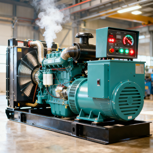
The airflow numbers become openings and machines at this step, and this is where designs quietly fail.
- Size the intake on the net free area, not the face area. A louver rated for 10,000 CFM may deliver only 6,000 after blade angle and mesh screens eat into the opening. Use the manufacturer’s net free area figure.
- Intake is about 1.5 times the radiator face area (2 times in hot climates). Exhaust around 1.2-1.5 times. Keep intake velocity under about 2-4 m/s, above which louvers start to whistle.
- Put the intake low on one wall and the exhaust high on the opposite wall, at least 3 m apart. Intake and exhaust on the same wall is the classic short-circuit.
- Keep the restriction within the set’s budget, typically about 125 Pa or 0.5 inches of water column for the intake path. Long ducts, screens, and dirty filters all eat into this number.
- Add 10-15 percent to the fan size for filter loading and blockage. A dirty louver can quietly lose a third of its airflow.
- Cold climates need a recirculation damper. A thermostatically controlled damper that recycles radiator discharge air keeps the room above freezing when the set is off, then opens fully on start.
Anastasia, a standby-power manager in Warsaw, kept a 400 kW set for a food-processing plant. The designer had installed motorized louvers that stayed fully open year-round to guarantee airflow. On a January night the room dropped to minus 8 °C, the jacket-water heater could not hold temperature against the draft, and the set failed its cold-start test the morning a storm took the grid. A thermostatically controlled damper that recirculates radiator air until the room reaches 10 °C fixed it, opening only enough to satisfy combustion. The set now starts at minus 20 °C outside.
Code and Standard Rules That Change the Design
Codes do not just suggest ventilation; they decide what counts as compliant, and the authority having jurisdiction has the final word.
NFPA 110, the standard for emergency and standby power systems, sets no fixed air-change number. It requires enough airflow to keep the engine running at full load on the hottest expected day, plus combustion air, per the manufacturer’s manual. The operational rules matter more than the arithmetic:
- Motorized louvers must fail open on power loss, typically with spring return. Standard fire dampers are prohibited in Level 1 ventilation paths. A damper that closes when the power fails will overheat the room and disable the generator during the very emergency it exists for.
- Ventilation fans must run on emergency power, not utility power.
- Ventilation-failure alarms must reach the remote annunciator with visible and audible signals.
- Level 1 generator rooms carry a 2-hour fire-resistance rating for walls, floors, ceilings, and doors. NFPA 37 calls for a 1-hour rating for standard engine rooms and exhaust outlets at least 10 feet from doors, windows, and building air intakes.
ISO 8528-5 sets the reference conditions on which the generator rating is based, and standards like AS 1668.2 and BS 7671 shape local air-change and temperature practice. The life-safety rules for the same room live in our generator room fire safety requirements guide.
The room design is one thing; the set it houses is another. See what a factory-direct build includes in our custom diesel generator: 9 specs guide
Common Ventilation Mistakes and the Field Fixes
Most overheating generator rooms are not short on air; they are misdirected. The recurring field failures look like this:
- Intake and exhaust on the same wall. Air short-circuits from outlet to inlet and never crosses the set.
- Radiator discharge is left to circulate in the room. The most common cause of summer overheating is fixed with a dedicated duct and a canvas connector.
- Louvers are sized on the face area instead of the net free area. The opening looks big and delivers a fraction of it.
- Fine mesh screens fitted for dust control. They cut the free area sharply and add restriction that was never budgeted for.
- Motorized dampers that fail closed. A code violation under NFPA 110 is a real hazard.
- Boilers or other combustion equipment sharing the room. The radiator fan pulls the room negative and starves it.
- No altitude or hot-climate correction. Raise airflow 10-15 percent per 1,000 m of altitude and double the intake allowance in hot climates.
- Dirty louvers never cleaned. A blocked louver can lose about 30 percent of its rated airflow over a season.
Miguel, a commissioning engineer in Manila, checked the intake louver before accepting a 500 kW plant room. The louver was rated for the airflow, but the mesh filter and blade angle cut its real free area by a third, and the radiator fan was pulling against far more restriction than the set allowed. Upsizing the louver and removing the fine mesh dropped the measured static pressure to a comfortable level, and the set stopped tripping on high coolant temperature in peak season. The measurement costs a day. The redesigned louver cost less than one service call.
Generator Room Ventilation Requirements: Quick-Reference Checklist
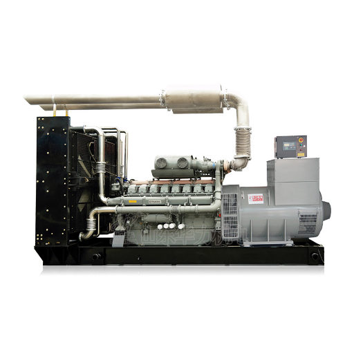
Work through these ten checks in order, and the design builds itself.
- Sum the three flows. Combustion plus radiator plus room heat removal.
- Use the set’s published data. Radiator airflow and heat rejection from the spec sheet beat any rule of thumb.
- Hold the room rise to about 10 °C above ambient. Keep the room at roughly 40-45 °C at full load.
- Duct the radiator discharge straight outside. Add a canvas connector at the radiator.
- Size intake louvers on the net free area. About 1.5 times the radiator face, 2 times in hot climates.
- Opposite-wall layout. Intake low, exhaust high, at least 3 m apart.
- Watch the numbers. Intake velocity under 2-4 m/s, restriction under about 125 Pa.
- Add margin and fail-safe behavior. Fans 10-15 percent larger, on emergency power, louvers fail open.
- Correct for site. Altitude, hot climate, and cold-climate recirculation dampers.
- Measure at commissioning. Static pressure and room temperature rise before you accept the room.
The load that makes the set run, and therefore produce the heat you are removing, is built in our how to make a generator load schedule guide. Whether the set runs in standby or continuously also changes how hard the room works, which is covered in our standby power system guide.
Frequently Asked Questions
How much ventilation does a generator room need?
A typical diesel generator room needs 50-80 m³/h per kW of total airflow, made up of combustion air at 5-7 m³/h per kW, radiator cooling air at 30-50 m³/h per kW, and room heat-removal air at 15-25 m³/h per kW. A 500 kW set needs about 35,000 m³/h.
How do I calculate generator room ventilation?
Calculate the heat-removal airflow with Q = heat to room ÷ (ρ × Cp × ΔT), add the engine’s combustion air, and add the radiator cooling air from the set’s specification sheet. The total intake is the sum of the three flows.
What temperature should a generator room be kept at?
Design the room to rise no more than about 10 °C above the worst-case ambient, and keep the room under roughly 40-45 °C at full load. Above that, the engine derates and the alternator insulation ages faster.
How many air changes per hour should a generator room have?
Around 15-20 air changes per hour during operation and at least 6 during standby are common benchmarks. NFPA 110 does not fix an air-change number; it requires heat-removal-based sizing using the manufacturer’s data.
What size louver does a generator room need?
An intake louver of about 1.5 times the radiator face area is a starting point, sized on net free area at a face velocity under 2-4 m/s. For a 500 kW set, that works out to roughly 3 m² of net free intake area.
What happens if a generator room is not ventilated?
The engine derates as its intake air heats up, high coolant-temperature trips shut the set down under load, and carbon monoxide can accumulate to dangerous levels. Radiator air recirculating in the room makes every one of these worse.
Conclusion
Calculating generator room ventilation is a three-flow problem, not a mystery. Size the combustion air for the engine, duct the radiator air straight outside, and run a heat balance for the room itself.
Here is what to remember:
- Sum three flows: combustion, radiator cooling, and room heat removal, totaling 50-80 m³/h per kW.
- Use the heat-balance formula for the room portion, holding the rise to about 10 °C.
- A 500 kW set lands near 35,000 m³/h of total intake, about 3 m² of louver net free area.
- Comply with the operational rules: louvers fail open, fans on emergency power, alarms on the annunciator.
- Measure at commissioning so the paper design is the real design.
Shandong Huali Electromechanical Co., Ltd. has built diesel generator sets from 8 kVA to 4,000 kVA for more than 25 years, and our engineers provide the room-ventilation numbers for every indoor and containerized installation we quote. Send us your project details and we will size the set and the room together.
