
Last updated:
A standby power system supplies selected loads when their normal electricity source fails. Start with the loads that need power and how long each can remain off. Then define the operating duty and the complete path that will restore their supply.
An engine that starts successfully may still leave a process unavailable. Transfer switches, controls, distribution, fuel and load sequencing all affect the result. This guide helps facility managers and project engineers turn those interfaces into a requirements sheet before comparing equipment quotes.
Key takeaways
- Classify loads and their interruption tolerance before choosing equipment.
- Keep operating duty, annual running hours and fuel autonomy separate.
- Select the complete power path, including transfer equipment and any UPS-protected branches.
- Check running demand and transient behavior separately; kW and kVA are different quantities.
- Define installed acceptance evidence alongside the purchase specification.
What a Standby Power System Must Deliver
The system boundary runs from the alternate source to the loads that need restoration. A generator-based arrangement normally includes generation, transfer equipment, protection and distribution, controls, starting support and fuel. Selected sensitive loads may also require an uninterruptible power supply (UPS).
On loss of normal supply, controls detect the failure and initiate the specified start sequence. Transfer equipment accepts the alternate source when its conditions are suitable, then supplies the selected circuits. Load sequencing may delay some equipment. When normal supply returns, the system follows its retransfer and generator cooldown sequence.
The timing must be defined at the load. Engine start time alone leaves out source qualification, switching, equipment restart and any process interlocks. Record which point the acceptance test will measure and what counts as successful restoration.
Illustrative scenario: A cold store has controls and a refrigeration compressor on backup power. Its engine starts, but the compressor has a separate restart delay. The requirements sheet must distinguish continuous control power from the motor’s permitted restart interval. This is a planning example, not a reported customer project.
For the wider facility context, see industrial power solutions. If you are preparing a purchase enquiry, send the selected-load list and operating requirements rather than asking for capacity alone.
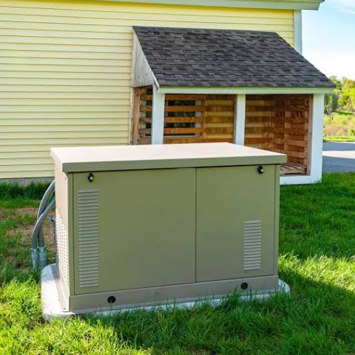
The equipment photographs in this guide are general exterior illustrations. They do not establish internal architecture, model performance, installation compliance or supplier ownership.
Classify the Loads Before Naming the System
Everyday use of “standby” is broader than a legal load classification. A business may call its whole backup installation a standby system even though individual circuits have different obligations. Start with the consequences of losing each load and identify the applicable local rules.
Separate load categories from equipment labels
In the United States, the National Electrical Code separates several load categories:
- Article 700: emergency systems.
- Article 701: legally required standby systems.
- Article 702: optional standby systems.
- Article 708: critical operations power systems.
These examples concern the United States. Use the rules adopted for the actual project location.
The Schneider Electric emergency power distribution guide distinguishes these categories and their system arrangements. Confirm the adopted edition, occupancy rules and local amendments with the project engineer and authority having jurisdiction (AHJ). Buying a generator carrying a “standby” rating does not settle that review.
NFPA 110 uses another set of terms. Level concerns the consequence of failure; Type concerns the permitted interruption; Class concerns operation without refueling or recharging. They describe different requirements and should appear as separate entries in a specification.
For example, the Cummins NFPA 110 overview explains Type 10 as a 10-second maximum interruption and Class 48 as 48 hours at rated load without refueling or recharging. That presentation references an older standard edition. These examples explain the labels; they do not establish what your facility currently requires.
Build a requirements matrix
Use a separate row for each group with a different consequence, restoration requirement or priority. Leave unconfirmed requirements visible instead of filling them with assumptions.
| Load group | Legal/design basis | Interruption tolerance | Required autonomy | Priority | Confirming party |
|---|---|---|---|---|---|
| Life-safety circuits | Confirm adopted rules | Confirm | Confirm | Engineer to assign | Engineer/AHJ |
| Process controls | Process risk assessment | Owner to specify | Confirm | Owner to assign | Process engineer |
| Motors and cooling | Restart/process requirements | Confirm sequence | Confirm | Engineer to assign | Mechanical/electrical team |
| Discretionary services | Business continuity decision | Owner to specify | Owner to specify | May be shed if approved | Facility owner |
Illustrative scenario: A clinic lists essential circuits, refrigeration, office equipment and comfort cooling. The engineer determines their actual classifications and distribution requirements. The owner then identifies which discretionary loads may be disconnected during limited capacity. Neither the building’s name nor one generator label provides that answer.
Ask who approves the matrix and who will maintain it when equipment changes. A new load can affect both capacity and the sequence needed to restore existing loads. Use hospital generator planning for application questions, while keeping the project’s approved requirements as the basis for design.
Match Standby Power System Duty to the Actual Operating Plan
The electrical load category and the generator’s operating rating answer different questions. The former concerns the supply obligations of selected loads. The latter describes the conditions under which the generating set’s declared output applies.
Describe the operating profile before comparing outputs
Record expected outages, testing and any planned operation while utility power remains available. Include whether the load is variable or constant and whether scheduled grid support or routine site generation is proposed. Ask for the exact model’s rating declaration rather than relying on a generic standby brochure.
| Rating family | Operating question to resolve | Evidence to request |
|---|---|---|
| Emergency standby power, ESP | Does the declared emergency-outage duty match the project? | Model-specific hours, load-profile and average-load conditions |
| Limited-time running power, LTP | Is a limited-duration, constant-load duty appropriate? | Declared operating-hour and output limits |
| Prime rated power, PRP | What variable-load operation is allowed? | Permitted profile, average-load conditions and maintenance requirements |
| Continuous operating power, COP | What constant-load output is declared? | Continuous-duty output and site-condition limits |
The Cummins generator-selection presentation illustrates how rating families differ by load profile and operating hours. The supplier must confirm the actual declaration for the offered set. A larger standby kW figure does not authorize every operating regime.
Keep three quantities separate: instantaneous rated output, average loading over the specified interval, and permitted operating hours. Fuel autonomy is a fourth issue. A tank that supports a long outage does not change the set’s declared duty, and an operating rating does not guarantee a particular tank runtime.
Do not turn prime or continuous ratings into a universal percentage of standby output. Nor should “unlimited hours” be read as freedom from maintenance, fuel, load or installation constraints. For a fuller terminology reference, see ISO 8528 generator ratings.
Illustrative scenario: A project initially specifies outage-only backup, then considers scheduled grid support. Before retaining the original selection, the team must revisit duty, permitted operation, maintenance and warranty conditions. The revised operating plan belongs in the supplier’s written review.
This distinction has current relevance. The IEA’s Powering Artificial Intelligence executive summary, published 14 October 2026, discusses grid constraints, non-firm connections and bring-your-own-power approaches. The practical implication for this guide is to check the intended operating regime when a project’s grid strategy changes. The report does not prescribe a generator rating or authorize local operation.
Before tender, assemble a duty statement covering outage hours, tests, planned generation, load profile, site conditions and applicable approvals. Ask the supplier to confirm its compatibility with the offered model and identify exclusions.
Choose the Architecture and Define Every Interface
Architecture determines how the selected loads receive power and what happens when equipment is unavailable. Compare arrangements using the approved load matrix, interruption tolerances and maintenance needs.
Compare complete power paths
| Arrangement | Reason to consider it | Interface to resolve | Failure or maintenance question |
|---|---|---|---|
| Single generator with ATS | Selected loads can tolerate the specified restoration interval | Source sensing, transfer, load priority and retransfer | What supplies the loads while the set or switch is isolated? |
| Generator plus UPS on selected branches | Some loads need continuity while the alternate source becomes available | UPS autonomy, input acceptance, bypass and recharge | Which loads remain protected in each bypass state? |
| Parallel generator plant | Project needs justify multiple sets and coordinated operation | Synchronizing, load sharing, protection and load shedding | What capacity and power path remain after a defined failure? |
An automatic transfer switch (ATS) transfers between acceptable sources; it does not store energy. A UPS can bridge an interruption for its connected loads within its designed conditions. Putting a UPS somewhere in the facility does not make every circuit interruption-free.
For parallel generation, count shared dependencies as well as generating sets. Common switchgear, controls, fuel or distribution can affect the result of losing one component. A spare set alone does not prove a particular availability level. The single versus parallel generators guide provides a more detailed architecture comparison.
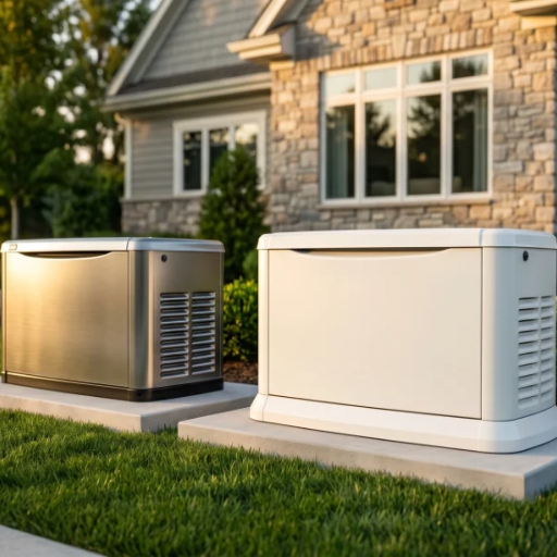
The exterior illustration above does not show the component connections. Use the project’s electrical one-line diagram to identify the actual source, transfer and distribution boundaries.
Review each operating state
Mark the diagram for normal operation, normal-source loss, generator supply, return to utility and maintenance isolation. Identify the loads energized in each state and the controls that permit or prevent switching. Ask the designer to explain what happens after a failed start, a rejected load step or loss of a control supply.
Have the electrical designer resolve neutral switching, earthing, fault protection and transfer transition. These choices depend on the complete installation. If the proposed transition involves utility paralleling, obtain the applicable utility review rather than treating it as a standard ATS feature.
Review the UPS input and recharge demand alongside the downstream load. A generator must supply the actual input profile under the intended operating modes. Refer detailed input-window, bypass and recharge checks to the generator and UPS compatibility guide.
In the earlier cold-store illustration, preserving control power and restarting the compressor are separate tasks. The one-line diagram should show the UPS-protected control branch, motor supply and restart controls. The acceptance sequence must test both paths.
For data-center generator applications, define the supported electrical and cooling loads together. The application name does not prove that a proposed topology meets a particular resilience requirement. Request a marked-up one-line diagram with supplier boundaries, load priorities and maintenance paths before comparing headline capacities.
Check Capacity Without Mixing kW, kVA and Starting Demand
A useful capacity review starts with a load schedule. Running demand, starting behavior and site conditions all matter, but they must remain distinct inputs. Adding a motor’s starting kVA directly to another load’s running kW produces no meaningful total.
Collect usable load data
| Input | What to record | Why it matters |
|---|---|---|
| Running demand | Measured or documented kW, kVA and power factor | Separates real and apparent power |
| Electrical supply | Voltage, frequency, phase and phase allocation | Defines the required supply and phase loading |
| Motor starting | Starting method, current, acceleration and sequence | Defines transient demand and load steps |
| Electronic loads | UPS, drives and other nonlinear input characteristics | Identifies waveform and compatibility checks |
| Process tolerance | Permitted voltage/frequency dip and recovery | Defines acceptable behavior at the load |
| Site conditions | Altitude, design temperatures and installation arrangement | Allows model-specific installed-output review |
| Operating sequence | Coincident loads, delays and approved shedding | Shows which demand can occur together |
| Growth | Named future loads and expected timing | Makes expansion assumptions reviewable |
Where measurements exist, retain their dates and operating conditions. A quiet production shift may not represent the site’s highest coincident demand. Where only nameplate data are available, label the assumption and have the supplier explain how it is used.
Use a dimensional check for steady-state demand
For a balanced three-phase sinusoidal load, apparent power is:
S (kVA) = √3 × line-to-line voltage (V) × line current (A) ÷ 1,000
Real power is:
P (kW) = S (kVA) × power factor
These relationships are set out in Schneider Electric’s basic electrical formulae. Use line-to-line voltage with line current in this form of the three-phase equation.
For an illustrative calculation, assume a balanced sinusoidal load at 400 V, 100 A and power factor 0.8. Apparent power is √3 × 400 × 100 ÷ 1,000 = 69.3 kVA, rounded to one decimal place. Real power is 69.3 × 0.8 = 55.4 kW, also rounded.
These are two descriptions of the same load. They are not quantities to add together. The result also does not select a generator: the example excludes starting behavior, other loads, installed conditions and required recovery performance.
For unbalanced or nonlinear loads, use suitable phase measurements and true-power data rather than extending the simplified assumptions without review. A single assumed power factor may conceal important differences between loads.
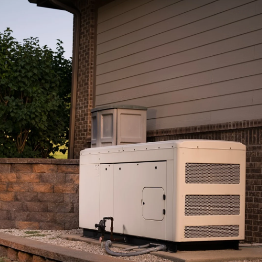
Submit the transient sequence for model-specific review
A set that covers steady running demand may still fail a load’s permitted dip or recovery requirement. Give the supplier the proposed sequence, existing load before each step, starting method and relevant equipment tolerances. Request the offered model’s sizing assessment and the assumptions behind it.
The Cummins T-030 application manual treats load effects and installation conditions as part of selection. Its February 2015 edition is an engineering reference, not proof of the latest local code requirements or a substitute for the offered model’s data.
Document coincidence and future expansion explicitly. Do not apply one diversity factor or reserve percentage to every facility. If capacity depends on shedding a discretionary load, identify the control that performs it and the behavior if that control fails.
Keep detailed starting calculations and alternator studies in the supporting engineering package. The decision needed here is whether the supplier has evaluated the actual running demand, sequence and installed conditions against the project’s acceptance limits.
Plan Fuel, Installation and Application Constraints
Fuel autonomy means usable operation under a defined demand and supply arrangement. It is not simply the tank’s labeled volume divided by an unspecified consumption rate. Ask for fuel-use data at relevant loads, usable storage assumptions, replenishment arrangements and any supporting pumps or controls.
On-site liquid storage and pipeline supply have different dependencies. Storage needs an approved installation, fuel management and a refill plan. A pipeline-fed arrangement needs its available pressure, capacity and disruption risks evaluated. Do not assume either remains available throughout the same event that affects utility electricity.
Fuel compatibility is model-specific. Obtain the engine manufacturer’s approval for the proposed fuel or blend and its conditions. A general statement about renewable diesel or alternative fuels is not evidence that every offered engine accepts them.
Check the installed environment
Review combustion and cooling air, hot-air recirculation, exhaust routing, access and drainage before freezing the layout. Acoustic treatment, ventilation and enclosure choices need coordination. A proposed remedy for noise must also leave the required airflow and maintenance access available.
Ask the supplier to identify permitted exhaust backpressure and cooling-system limits for the exact configuration. Have the installation designer check the proposed routes and equipment against those values. Record who supplies ducts, louvers, silencers, flexible connections, supports and commissioning measurements.
Application requirements should remain specific. A hospital project needs its approved load categories and continuity arrangements. A data center needs coordinated electrical, UPS and cooling behavior. An industrial process needs its restart logic and acceptable interruption identified.
None has one universal generator size or fuel-runtime requirement merely because of its industry label.
Compare physical risks alongside electrical performance: flood exposure, service access, security, fuel delivery and the ability to isolate equipment for maintenance. The owner should know which approved loads remain supplied during planned work and which require a temporary arrangement.
Finally, confirm the permitted operating regime with the responsible local parties. Outage backup, routine generation and grid support may have different approval conditions. Record those conditions in the duty statement and purchase documents instead of leaving them as assumptions between supplier and installer.
Turn the Design into a Quote and Acceptance Checklist
A comparable quotation must describe the equipment and the work needed to make it function at the intended loads. A generator-only price cannot establish the installed system cost or acceptance scope.
Request an itemized technical submission
Use this checklist when reviewing standby generator options:
- Exact set, engine, alternator and controller identification, with the declared rating and site conditions.
- Load schedule, proposed sequence and model-specific sizing/transient assessment.
- One-line diagram, transfer arrangement, protection and control interfaces.
- Fuel, starting, cooling, exhaust and enclosure scope with installation limits.
- Clearly assigned supply, installation, commissioning and documentation responsibilities.
- Test procedures, acceptance criteria, warranty conditions and maintenance requirements.
- Dated delivery milestones, exclusions and assumptions, including any owner-supplied equipment.
Put competing offers into the same scope table. For each item, mark included, excluded or awaiting clarification, and name the party responsible for any exclusion. Compare output only after matching the declared duty, voltage, frequency and site conditions.
If one offer includes transfer equipment but another excludes it, request a revised scope or a separately priced interface package. If a supplier cannot demonstrate the required load sequence, keep that technical question open while reviewing price. Resolving the uncertainty on paper is more useful than assuming the largest nameplate covers it.
Require clarification where two suppliers use different ratings or exclude different interfaces. Do not assume a lower quote includes the same ATS, switchgear, fuel system, site works or tests.
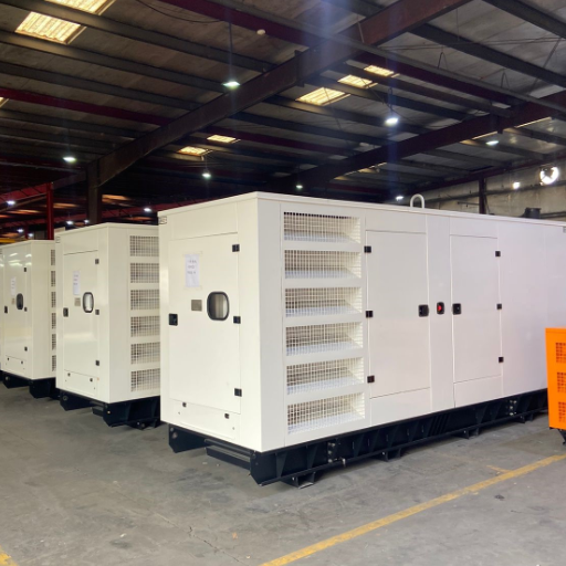
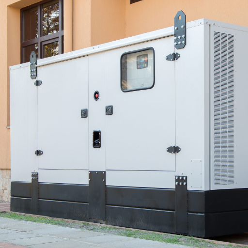
The enclosure photograph is illustrative; it is not evidence of a particular factory, supplier package or tested installation.
Define evidence of installed performance
Separate factory testing from installed acceptance. A factory report cannot by itself establish the behavior of the site’s transfer equipment, cabling, controls and connected loads. Brown University’s standby power specification is an owner-specific example combining equipment submittals with field testing. Its particular choices are not universal project requirements.
Agree how to witness normal-source loss, source readiness, transfer, staged load restoration and return to normal supply. Define the relevant failure cases, alarm checks and maintenance states. Record measurements at the points that establish the required result, and assign responsibility for resolving deviations.
Build a test sheet that makes each result traceable to an approved requirement. A useful starting template is:
| Test record | Information to enter before the test | Result to retain |
|---|---|---|
| Normal-source loss | Starting load, event trigger and timing reference | Event log and measured restoration at the designated loads |
| Load restoration | Approved sequence, starting method and acceptance limits | Applied load steps, voltage/frequency response and equipment restart observations |
| Return to normal | Retransfer conditions and process constraints | Switching record, affected loads and completed return sequence |
| Defined failure case | Safe test method, expected alarm and permitted load shedding | Observed alarm, control response and remaining supplied loads |
| Maintenance state | Isolation procedure and required temporary supply | Confirmed power path, restrictions and restoration checks |
Agree the safe test method before work starts. Assign a witness and a person who can stop the test if the process or equipment is at risk. This template does not authorize switching work or prescribe a test interval.
For each exception, record the requirement, observed result, corrective action and retest reference. A generator running at the end of the test does not close an unresolved failure to restore a required load. Keep incomplete items open with an owner and an agreed resolution.
At handover, collect the approved one-line diagram, control settings, equipment manuals and final test records. Identify who can change settings and how the load matrix will be reviewed after later additions. Those records let the facility team distinguish a new operating problem from a change to the original design basis.
Keep test frequencies tied to the adopted requirements, manufacturer instructions and approved maintenance plan. An exercise run and an end-to-end functional test answer different questions. Retain test settings, results, exceptions and corrective actions so the next review can reproduce the basis for acceptance.
Can standby and emergency loads share a generator?
The load categories alone do not settle the architecture. Have the engineer review required separation, capacity, priorities, protection and transfer arrangements under the applicable rules. Do not assume shared generation permits shared distribution or unrestricted discretionary loading.
Does a UPS remove the need to check transfer time?
No. Verify the complete path for each protected load, including UPS autonomy, input acceptance and bypass states. Loads outside that path retain their own interruption and restart requirements.
Is rated kVA enough to select the system?
No. Review real power, apparent power, operating duty, load sequence, transient limits and site conditions. The final package must demonstrate the required behavior at the selected loads.
A useful standby power system specification therefore joins the load matrix, duty statement, one-line diagram and acceptance plan. To discuss a proposed supply package with Shandong Huali Electromechanical Co., Ltd. (ShanHua), send your project requirements with those documents and ask for a written scope response.
