
A generator heat exchanger is a liquid-to-liquid device that moves engine heat into a second water loop instead of into air. On a land-based set you’ll meet two families of them, shell-and-tube and plate, and choosing between the two is a decision about water quality and cleanability rather than about thermal performance. The lube oil cooler is usually the second exchanger in the same circuit, and it’s the one most specification sheets forget.
This page covers land-based and industrial configurations and how to select between exchanger types. For marine installations, and for the static head rule that decides when a heat exchanger has to replace a radiator, see our guide to generator heat exchanger cooling on our sister site.
Here’s the part that decides most projects. A heat exchanger doesn’t create cooling. It relocates heat into a loop that belongs to somebody else, and that loop arrives with its own water chemistry, its own pumps and its own fouling.
Choosing a generator heat exchanger isn’t buying a component. It’s accepting ownership of a second cooling circuit. For a plant engineer, that’s the whole decision.
Key Takeaways
- A generator heat exchanger is a liquid-to-liquid unit that rejects jacket water and lube oil heat into a secondary water loop. The two fluids never mix.
- Shell and tube suits dirty or fouling-prone water because the bundle can be rodded out by hand. Plate suits clean, closed loops and is far more compact, but a brazed plate can’t be cleaned at all.
- The lube oil cooler is a second, separate exchanger on most large sets. Lube oil carries heat that the jacket circuit never sees.
- Approach temperature, not surface area, is what drives exchanger size. A plate unit can run a 1-2 °C approach; a shell and tube typically needs 5-10 °C.
- Never specify an exchanger on water temperature alone. Flow rate, allowable pressure drop, design pressure and materials all belong on the data sheet.
What a Generator Heat Exchanger Does on a Land-Based Set
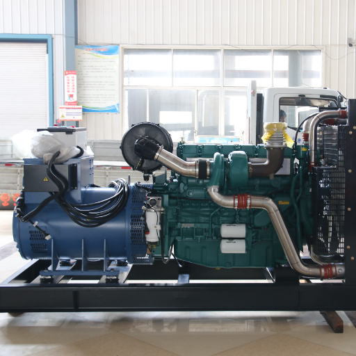
On a land-based generator, an exchanger is usually chosen for one of two reasons. Either the site has a usable water supply but no workable path to outside air, or the waste heat is going to be recovered rather than thrown away. Both cases move the heat into water, and both require a second loop to be designed, owned and maintained.
That second loop is why this component attracts so much trouble. A radiator gives its heat to the atmosphere and the job is finished at the fan. An exchanger gives its heat to a pump, a strainer, a pipe run and a water treatment regime that somebody has to look after.
The two heat exchangers on a large set
Large sets reject heat through more than one circuit, and a complete liquid-to-liquid design has to account for both. Kohler Power Systems sets this out in its remote cooling design paper: the jacket water circuit cools the engine block and head, and the charge air circuit cools the air leaving the turbocharger. Heat rejection on the high-temperature side is the jacket water plus the oil cooler. On the low-temperature side it’s the aftercooler.
That sentence explains why two exchangers appear on the same machine. The jacket water exchanger handles the bulk of the liquid heat load. The generator oil cooler handles the oil circuit and is a separate unit with its own duty. When a specifier orders “the heat exchanger” in the singular, the oil cooler is the piece that gets left off the schedule.
For the rest of the circuit around these components, see our guide to the generator cooling system.
Heat exchanger vs radiator, in one line
A radiator rejects heat to air using a fan and a finned core, needs no water supply, and costs less. A generator heat exchanger rejects the same heat to water using no fan, suits enclosed rooms, and needs a continuous water supply it can’t do without. The detailed decision rule belongs on the guide linked above. If your site has airflow and the radiator simply sits too far from the engine, our generator radiator guide covers that case instead.
Need a cooling configuration sized to your site? Send our engineers your ambient conditions, water source and room constraints, and we’ll specify the arrangement with the set. Talk to our engineering team →
Shell and Tube vs Plate: Choosing the Type
The main heat exchanger types are grouped by construction: shell and tube, plate, double-pipe and air-cooled. The exact count varies by source, and the air-cooled family is really a radiator. For generator duty the choice comes down to the first two, and the deciding factors are water quality and how the unit will be cleaned.
This is the section the SERP is missing. Existing pages explain what an exchanger is and why you’d fit one, but almost none tells a specifying engineer which construction to order.
Shell and tube heat exchangers: for dirty water and easy cleaning
A shell and tube heat exchanger puts one fluid through a bundle of tubes and the other through the shell around them. Baffles force the shell-side fluid across the tubes instead of straight along them, which raises turbulence and improves heat transfer. The construction is defined by standards published by the Tubular Exchanger Manufacturers Association, the body most suppliers specify against.
The reason to choose it on a generator is maintenance. Each tube can be cleaned by pushing a rod through it during a shutdown, which no other construction allows. Cooling tower water, river water and anything carrying suspended solids will foul the surface, and fouling is the most common way a correctly sized exchanger turns into an undersized one. If the water is dirty and the set matters, this is the type to order.
The trade-offs are size and approach. A shell-and-tube unit needs a larger footprint for the same duty, and typically a wider temperature gap between the fluids, usually in the region of 5-10 °C. It’s heavier, and the bundle has to be pulled for a proper clean.
Plate: compact, tight approach, clean water only
A plate heat exchanger stacks corrugated metal plates in a frame. The corrugation creates turbulence at low flow, and the large surface area in a small volume gives a much tighter approach temperature, commonly down to 1-2 °C. In a tight plant room, that compactness is often the reason the component fits at all.
The limitation is the gaps. Plate units have narrow flow channels, so anything coarse in the water blocks them. They suit closed loops, treated water and building chilled water systems. They don’t suit an open cooling tower loop or a river supply without filtration, and manufacturer guidance is consistent on this point.
Gasketed, brazed and welded: what you can actually clean
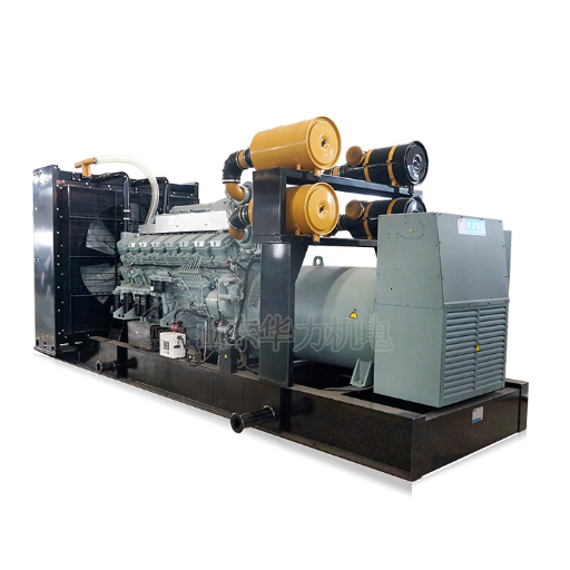
A gasketed plate heat exchanger is the version you can open. The plates are sealed by elastomer gaskets and the whole stack opens for inspection and manual cleaning. Standard EPDM gaskets suit water up to roughly 150 °C; nitrile gaskets sit lower, around 110 °C.
The other two builds trade that access for capability. A brazed plate unit is vacuum-brazed with copper or nickel filler, so it handles higher temperatures and pressures in a very small envelope, but it can’t be opened or mechanically cleaned. That makes it a disposable item on a fouling duty. A welded plate unit takes high temperature and pressure without gasket limits and can be cleaned chemically, but not by hand.
A compact plate exchanger is often the cheapest way to hit a tight approach. On a dirty loop it’s also the fastest way to a callout.
Priya learned that on a district cooling project in Muscat, where a brazed unit was fitted to an open tower loop to save plant room space. Two summers later the channels were scaled solid and the set was derating under load. The replacement had to be a shell-and-tube exchanger twice the footprint, and the saving on the exchanger was spent on the retrofit.
Table 1: Choosing a construction
| Factor | Shell and tube | Gasketed plate | Brazed plate |
|---|---|---|---|
| Typical approach temperature | 5-10 °C | 1-2 °C | 1-2 °C |
| Fouling tolerance | High | Low | Low |
| Cleanable in place | Yes, tube by tube | Yes, stack opens | No |
| Gasket temperature limit | Not applicable | ~150 °C EPDM | Not applicable |
| Footprint | Large | Small | Very small |
| Best water quality | Dirty, filtered only | Clean, closed loop | Clean, closed loop |
| Failure mode | Leaking tube | Gasket weep | Internal, no repair |
| Relative cost | Higher | Moderate | Lower |
Table 2: matching the type to the site
| Site condition | Recommended | Why |
|---|---|---|
| Open cooling tower water | Shell and tube | Rodded clean; tolerates suspended solids |
| Building chilled water, closed loop | Gasketed plate | Clean water, tight approach, small footprint |
| River or pond supply | Shell and tube with strainer | Solids will reach the exchanger |
| Tight basement plant room | Gasketed or brazed plate | Fits where a shell cannot |
| High secondary water temperature | Shell and tube or welded plate | Gasket limits rule out gasketed plate |
| Standby set, low running hours | Gasketed plate | Opens for inspection between long idle periods |
The Lube Oil Cooler
The lube oil cooler is the second exchanger on a large generator and the one that receives the least attention. It’s a separate component with its own duty, its own water connection and its own failure mode, and it’s covered by almost none of the material published on this topic.
Why lube oil needs its own cooler
Oil does more than lubricate. It carries heat away from the bearings, the piston undersides and the turbocharger, and it degrades fast above its design temperature. A conventional engine heat balance puts roughly a third of the fuel energy into useful work, roughly a third into exhaust, and the remainder into heat that the coolant and the oil must remove together. If that oil-side heat has nowhere to go, oil temperature climbs, viscosity falls, and the oil film protecting the bearings thins out.
The consequences are gradual rather than dramatic, which is why the component gets neglected. Oil that runs hot oxidises faster, forms varnish, and shortens the drain interval. By the time bearing wear shows up on a vibration reading, the cooler has usually been undersized or fouled for months.
Oil-to-water or oil-to-air
Oil-to-water units are the default on larger sets and on anything with an existing water circuit. They’re compact and hold oil temperature stable regardless of ambient, which matters in a hot plant room. The cost is that the oil cooler now depends on the same secondary loop as the jacket exchanger, so a cooling water fault takes out both circuits at once.
Oil-to-air units use a finned core and a fan, need no water, and are common on smaller and mobile sets. They’re simpler and independent of the water side. They’re also temperature-following: on a 45 °C day the oil runs hotter than it would at 15 °C, which is worth knowing before a set is rated for continuous duty in a hot climate. Our guide to altitude and temperature derating covers how that ambient penalty is calculated.
Either way, the oil cooler belongs on the cooling system drawing, not on an accessory list. When it’s omitted, it resurfaces as an unexplained high oil temperature alarm under sustained load.
Sizing a Generator Heat Exchanger
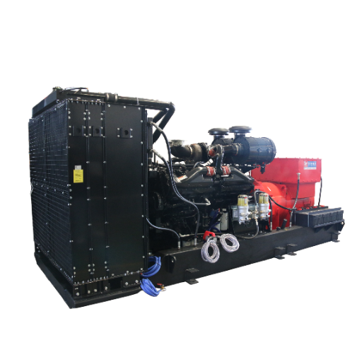
Sizing starts on the engine side, not at a supplier’s catalogue. The exchanger has to carry a specific heat load, and the first step is to establish what that load is rather than to pick a unit because it looks about right.
Start from the heat rejection, not the catalogue
The heat balance is conventional. Heat carried away by a fluid equals the mass flow multiplied by the fluid’s specific heat capacity and the temperature rise:
Q = ṁ × cp × ΔT
Where Q is the heat rejection rate, ṁ is the mass flow, cp is the specific heat capacity, and ΔT is the permitted temperature rise across the circuit. The heat rejection figure for the engine is published by the manufacturer, and it’s the number a supplier should be asked to size against. Add a modest margin for transient overload rather than sizing to the exact duty.
An exchanger that’s correct on paper but hot on site is nearly always a flow problem rather than a surface area problem. Before replacing anything, confirm the secondary loop is delivering the design flow.
Approach temperature and the water side
Approach temperature is the difference between the temperatures of the hot and cold fluids leaving the exchanger. It’s the single figure that governs how large the unit must be, and it’s where most of the cost sits. A tight approach means more surface area, a bigger frame and a higher price. It also means the exchanger can still perform when the secondary water warms up on a hot afternoon.
That last point is the one projects miss. An exchanger sized with a generous approach may pass every test on commissioning day, only to fail in July, because the cooling water itself has warmed and the gap between the two fluids has closed. Our generator overheating guide covers how that shows up as a fault on site.
The water side then sets the rest of the envelope. Flow rate is set by the heat load and the permitted temperature rise, not by the pipe size that happens to exist. Allowable pressure drop has to suit the secondary pump curve, which is the real constraint.
Design pressure and temperature come from the system the unit will sit in, including any expansion tank head. Materials follow the water: plate units are normally 316L stainless, while shell and tube units vary from carbon steel shells with copper alloy or stainless tubes. See our generator coolant guide for the fluid side of the same decision.
Table 3: what a heat exchanger data sheet must state
| Item | What to state | Why it matters |
|---|---|---|
| Heat rejection duty | kW, from the engine data sheet | Sets the size; an assumed figure undersizes the unit |
| Secondary water inlet temperature | Worst-case summer value | Drives the approach, not the annual average |
| Maximum outlet temperature | Site or discharge limit | Caps the usable temperature rise |
| Flow rate | m³/h or L/min | Determines velocity and cleaning performance |
| Allowable pressure drop | kPa or bar | Must suit the secondary pump curve |
| Design pressure and temperature | bar, °C | Sets the frame and gasket rating |
| Materials | Plates, tubes, shell, gaskets | Must match the water chemistry |
| Connection sizes and orientation | DN, port layout | Determines whether it fits the pipe run |
Land-Based Configurations
Where the second loop sends the heat carries the most project risk, because it usually belongs to somebody outside the generator scope. Three arrangements cover most land-based installations.
Basement and enclosed plant rooms
An interior plant room with no exterior wall is the classic case for a liquid-to-liquid exchanger, and usually the reason the component is on the drawing at all. The room can’t supply enough cooling air, so the heat has to leave through a pipe.
An exchanger removes the airflow requirement, but not the need for ventilation entirely. Combustion air still has to reach the engine, and radiant heat still has to clear the room.
Cooling towers, chilled water and heat recovery
A cooling tower is the standard sink for a site that already has one, but it’s an open loop and can’t be piped into a treated, glycol-protected engine circuit. The two are separated by an exchanger, and that exchanger is the one on this page most likely to need rodding out.
Building chilled water is the urban equivalent. The generator rejects into it through an intermediate exchanger, which can cut the room’s cooling airflow requirement substantially, provided the mechanical team agreed to absorb the load at design stage.
Recovering the heat instead of rejecting it is often the most valuable option. Exhaust gas carries roughly a third of the fuel energy, and an exchanger on the exhaust path can put it to work in a district heating loop or a process.
Specifying and Maintaining a Generator Heat Exchanger
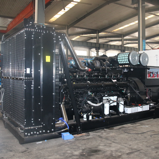
Two habits separate installations that last from installations that become a maintenance liability: specifying the water side properly, and cleaning the exchanger on a schedule rather than on a fault.
Cleaning and fouling on the water side
Fouling is the slow failure. Dissolved minerals precipitate onto hot surfaces and insulate them, and the loss of heat transfer is significant once a layer has formed. Suspended solids do a version of the same thing, and biological growth in an open loop does it faster still. In each case the exchanger was correctly sized when installed and is undersized a year later.
The practical response is a schedule tied to water quality rather than a fixed date. A closed loop may need annual attention; an open tower loop will need more. Strainers protect the exchanger as well as the pump, and a coarse screen on the inlet prevents the debris that blocks plate channels permanently. Where the water is aggressive, sacrificial anodes protect the areas where dissimilar metals meet.
Chemical cleaning suits welded and gasketed units and the shell side, which can’t be reached mechanically. Physical cleaning, by pulling the bundle or opening the stack, remains the only way to clear a hard scale layer. That’s the whole argument for choosing shell and tube in the first place.
When a radiator is the better answer
Not every set needs an exchanger. Specifying one where a radiator would work adds a pump, a strainer, a water treatment regime and a freeze risk in exchange for nothing. If the room can supply cooling air, an integral radiator is simpler, cheaper and needs no water at all.
If the radiator simply has to sit further from the engine than the set allows, a remote radiator usually answers the question without a second loop. Our generator radiator guide walks through that decision and the head limits that come with it. To prove the configuration under real load rather than on paper, load bank testing is how that’s done before handover.
Conclusion
A generator heat exchanger is a straightforward component made complicated by the second circuit it creates. Get the type right and it runs for years. Get it wrong and it becomes a recurring callout.
The decisions that matter, in order:
- Choose the construction for the water, not the duty. Shell and tube where the water is dirty or the exchanger must be rodded clean. Plate where the loop is closed, clean and short of space.
- Include the lube oil cooler in the scope from the start. It’s a separate exchanger with its own heat load, and it’s the one most often missing from the schedule.
- Size from the engine’s published heat rejection, with a margin, and check the approach against worst-case summer water temperature rather than a commissioning-day reading.
- Specify the full water side. Flow, pressure drop, design pressure and materials all belong on the data sheet alongside the temperatures.
- Clean on a schedule. Fouling is the most common reason a correctly sized generator heat exchanger stops working.
Shandong Huali has manufactured diesel generator sets from 8 kVA to 4,000 kVA since 1999. Our engineering team specifies the cooling arrangement, including generator heat exchangers and lube oil coolers, against the site conditions each project actually has. Send us your ambient, water source and room constraints, and we’ll size the configuration with the set. Contact our engineers →
