
A power conversion system for energy storage is the bidirectional power electronics unit that converts DC from the battery into grid-quality AC during discharge, and AC back into DC during charging. It also controls voltage, frequency, and reactive power, making it the component that turns stored energy into usable electricity.
It is also the most expensive component that project teams routinely spec in a hurry.
Tomas, an EPC project engineer in Chile, learned this on a 4 MWh commercial storage project in 2024. His team sized the PCS straight from the battery nameplate: 4,000 kWh over 2 hours meant 2,000 kW. No allowance for conversion losses, no safety margin. At commissioning, the system could not hold its contracted 2-hour discharge. The retrofit, swapping in a correctly sized 2.5 MW unit plus new switchgear, cost $90,000 and two months of delay.
Buyers obsess over battery cells and per-kWh pricing, then treat the PCS as a line item. That is backwards. The battery stores energy, but the PCS decides how much of it you actually get, how fast, and whether the grid accepts it. This guide explains how a PCS works, how to choose between architectures and grid modes, and how to size one correctly, with a full worked example.
Key Takeaways
- A PCS is a bidirectional converter, not a standard inverter; it charges and discharges, and it provides grid-support functions.
- Modern units reach 97-98.5% efficiency at rated load, with ratings from 125 kW to 7.5 MW and DC windows of 800-1500V.
- Size a PCS from energy and duration: PCS kW = usable kWh ÷ hours ÷ efficiency (0.96) × safety factor (1.1).
- Grid-following units fail on weak grids; grid-forming units hold up below short circuit ratio 3 but cost more.
- In hybrid plants, the PCS is what lets a battery shave peaks so diesel gensets run loaded and efficient.
What Is a Power Conversion System (PCS)?
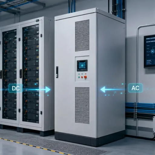
A power conversion system (PCS) is the bidirectional converter that sits between a battery and the AC grid in a battery energy storage system (BESS). During discharge it converts battery DC to grid-synchronized AC. During charge it rectifies grid AC back to DC. It regulates voltage, frequency, active and reactive power in both directions.
The power chain looks like this: battery racks feed the PCS on the DC side, the PCS feeds a step-up transformer on the AC side, and the transformer connects to the grid or site bus. Ratings run from 125 kW commercial units to 7.5 MW utility blocks, with DC voltage windows typically spanning 800-1500V, according to the BESS Manufacturers PCS comparison.
PCS vs a Standard Inverter
Calling a PCS “an inverter” undersells it and leads to bad specs. The differences matter:
| Attribute | Standard PV Inverter | PCS for Energy Storage |
|---|---|---|
| Power flow | One direction (DC to AC) | Bidirectional (charge and discharge) |
| Response time | Seconds | Milliseconds |
| Reactive power | Limited | Four-quadrant, full range |
| Grid services | Basic anti-islanding | Frequency regulation, black start options |
| Control interface | Solar MPPT logic | Coordinates with BMS and EMS |
Planning a storage or hybrid project? Our engineers size PCS and genset combinations as one system, so nothing gets underspecced at the interface. Talk to our engineering team →
How a PCS Works with the BMS and EMS
A BESS has three brains, and confusing them causes real project failures. The simplest accurate model: the battery stores energy, the BMS keeps it safe, the PCS makes it usable, and the EMS decides when and why to use it, as Boostess Energy’s component guide puts it.
During a discharge cycle, the EMS sends a power setpoint to the PCS. The PCS checks with the BMS that cell voltages, temperatures, and state of charge allow it, then delivers the power. If the BMS reports a fault, the PCS ramps down in milliseconds.
The practical warning: integration failures between these three systems are a leading cause of commissioning delays. Protocol mismatches between a PCS from one vendor and a BMS from another can stall a project for weeks. Specify the communication protocol (usually Modbus TCP or CAN) and confirm factory integration testing before the equipment ships.
Inside the PCS: Topology, Cooling, and Protection
Datasheets rarely explain what is inside the cabinet, but three design choices shape efficiency, reliability, and price.
Two-Level vs Three-Level Converter Topology
Older and cheaper PCS units use two-level converter bridges. They are simple and proven, but they switch the full DC voltage in every pulse, which raises switching losses and output distortion. Most modern units above 250 kW use three-level topologies (NPC or T-type). Three-level designs halve the voltage stress on each semiconductor, cut harmonic distortion, and lift efficiency by roughly half a percentage point at partial load. The newest premium units go further with silicon carbide (SiC) devices, pushing peak efficiency toward 99% and shrinking the cooling system. SiC costs more today; the premium buys efficiency and power density, not extra features.
Air vs Liquid Cooling
| Attribute | Air-Cooled | Liquid-Cooled |
|---|---|---|
| Typical range | Up to ~250 kW | 250 kW and above |
| Maintenance | Filter changes, fan service | Coolant checks, pump service |
| Dust and humidity tolerance | Lower (open airflow path) | Higher (sealed power stage) |
| Noise | Higher (fans) | Lower |
| Best fit | Clean indoor rooms | Containers, dusty or tropical sites |
For containerized systems in mining and desert environments, liquid cooling with a sealed power stage is worth the premium. Dust ingestion is a leading cause of power-electronics failure on remote sites, and fan filters only delay it.
Protection and Grid Coordination
A PCS coordinates protection on both sides. On the DC side: fuse or breaker coordination with the battery racks, ground-fault detection, and pre-charge circuits that limit inrush when connecting to the DC bus. On the AC side: anti-islanding detection, over/under voltage and frequency trips per the local grid code, and fault ride-through settings. Utility-scale designs integrate this with medium-voltage switchgear and the step-up transformer, exactly the single-line architecture shown in ABB’s BESS design documentation. Ask the vendor for the protection coordination study before commissioning, not after the first nuisance trip.
PCS Architectures: Centralized vs String vs Modular
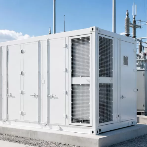
| Attribute | Centralized | String | Modular |
|---|---|---|---|
| Unit size | 1-10 MW | 125-350 kW | 50-250 kW blocks |
| Cost per kW | Lowest | Medium | Highest |
| Single point of failure | Yes, whole block | No, one string | No, one module |
| Maintenance | Specialized, site-level | Swap a unit in hours | Hot-swappable modules |
| Best fit | Utility-scale, flat demand | Commercial, varied loads | High-availability sites |
Centralized units dominate large utility projects because nothing beats their cost per kW at 5 MW and above. String architectures win in commercial and industrial projects, where loads vary and losing one 250 kW string out of eight barely registers. ABB’s utility-scale BESS design documentation shows how centralized blocks integrate with medium-voltage transformers and protection at the 4 MWh scale.
AC-Coupled vs DC-Coupled Storage
Where the PCS sits relative to other generation defines the system topology:
| Attribute | AC-Coupled | DC-Coupled |
|---|---|---|
| PCS connection | Battery has its own PCS on the AC bus | Battery shares a hybrid inverter with solar DC |
| Retrofit to existing sites | Easy; adds alongside existing equipment | Difficult; usually requires replacing the inverter |
| Conversion steps | More (DC-AC-DC-AC round trip) | Fewer (one conversion for solar-to-battery) |
| Round-trip efficiency | Lower by 2-4 points | Higher |
| Diesel hybrid compatibility | Natural fit; gensets and PCS share the AC bus | Rare; hybrid inverters assume solar DC |
For retrofits and for any diesel hybrid plant, AC coupling is the default answer: the battery PCS simply joins the existing AC bus next to the gensets. DC coupling earns its complexity in new solar-plus-storage builds, where it avoids one full conversion stage. A resort in the Philippines learned this the expensive way when it tried to DC-couple a battery onto a four-year-old solar array; the existing inverters could not accept it, and the redesign cost more than the efficiency gain will ever repay.
Grid-Forming vs Grid-Following: What Buyers Need to Know
This choice decides whether your system works on a weak grid, and most supplier brochures bury it in a footnote.
A grid-following (GFL) PCS locks onto the grid’s voltage and frequency using a phase-locked loop, then injects current. It assumes a strong grid exists to follow. A grid-forming (GFM) PCS behaves like a voltage source: it sets the voltage and frequency reference itself, the way a synchronous generator does.
| Attribute | Grid-Following | Grid-Forming |
|---|---|---|
| Grid reference | Follows the grid (PLL) | Creates the reference |
| Weak grid (SCR below 3) | Unstable, may trip | Stable operation |
| Islanded operation | Not possible alone | Yes, with local source or storage |
| Black start | No | Yes, if supported |
| Islanding detection | Fast (0.4-0.9s) | Slower (up to ~1.9s) |
| Cost | Baseline | Premium, historically up to 5x, now closer to 30-100% |
The research behind these rows is solid. A comparative study in MDPI Energies found GFL inverters degrade below a short circuit ratio (SCR) of about 10 and lose stability near SCR 3, while GFM units stay stable in weak grids. The trade-off: GFM detection of unintentional islanding takes two to four times longer. On cost, IRENA’s mini-grid outlook pegs grid-forming inverters at $500-1,200 per kVA, a premium that has narrowed as the technology matures.
The buyer’s rule is simple. Strong utility grid, normal interconnection: grid-following is fine and cheaper. Weak feeder, island grid, mining site, or any microgrid that must run islanded: specify grid-forming or verify the vendor’s weak-grid performance in writing.
How to Size a PCS for Energy Storage
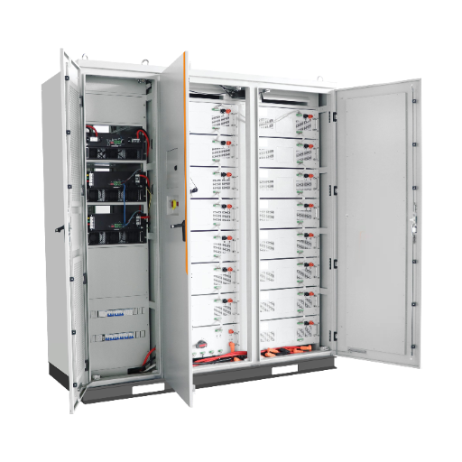
Here is the procedure that would have saved Tomas his $90,000. Five steps:
- Start from energy and duration. Usable battery capacity ÷ discharge hours = base power. A 4,000 kWh usable pack delivering over 2 hours needs 2,000 kW.
- Adjust for efficiency. Divide by round conversion efficiency, about 0.96: 2,000 ÷ 0.96 = 2,083 kW.
- Apply a safety factor. Multiply by 1.1 for temperature derating, aging, and tolerance: 2,083 × 1.1 = 2,292 kW.
- Check reactive power and overload. If the grid code requires power factor support at full real power, add headroom; kVA must cover both. Confirm the overload rating covers motor starting or surge loads.
- Match the DC window and C-rate. The battery string voltage must sit inside the PCS’s 800-1500V DC range across the whole state-of-charge swing, and the battery’s C-rate must sustain the PCS’s full power.
Worked example: 4 MWh usable, 2-hour duration, PF 0.95 requirement. Base 2,000 kW, adjusted 2,083 kW, with safety factor 2,292 kW. Add reactive headroom and you specify a 2.5 MW PCS, not the 2 MW unit that came off the nameplate math.
Two sizing mistakes repeat across projects. First, sizing from battery nameplate kWh instead of usable kWh after depth-of-discharge limits. Second, reading 98% PCS efficiency as system efficiency. The PCS loss compounds with battery round-trip efficiency, transformer losses, and auxiliary loads; a 98% PCS inside a system that delivers 88% end to end is normal, not a defect.
Reading a PCS Datasheet: The Specs That Matter
| Datasheet Row | What It Actually Tells You |
|---|---|
| Rated power (kW/kVA) | Continuous real power; check whether kVA covers reactive support at full kW |
| Max efficiency | Peak only; ask for the efficiency curve at 25-50% load, where storage often operates |
| DC voltage range | Must cover your battery string from full to empty |
| THDi (current distortion) | Below 3% is good; weak grids need better |
| Overload rating | Typically 110-120% for seconds to minutes; critical for motor loads |
| Power factor range | Four-quadrant, 0.8 leading/lagging or better for grid code compliance |
| Thermal derating | Output loss above 40-45°C; decisive in tropical and container installations |
| Certifications | IEC 62477 (converter safety), IEEE 1547 / UL 1741 (North American interconnection), plus local grid codes |
The derating row deserves emphasis. A PCS rated 500 kW at 25°C may deliver 425 kW inside a 45°C container in the Middle East. If your project sits in heat, size from the derated curve, not the headline number.
PCS in Hybrid Systems: Pairing Storage with Diesel Generation
Every ranking article on this topic assumes solar panels on the other side of the PCS. A large share of real projects, especially in mining, island grids, and off-grid industry, pair the battery with diesel gensets instead. This is where PCS selection gets interesting, and where the solar-only guides go silent.
In a diesel-plus-storage plant, the PCS does three jobs. It shaves peaks so gensets run at a steady, efficient load instead of chasing demand swings. It smooths transients, absorbing step loads in milliseconds while the genset governor catches up. And it handles seamless transfer, keeping the bus alive during genset start, stop, and rotation.
There is a maintenance dividend too. Gensets that idle along at 20-30% load suffer wet stacking, the unburned-fuel fouling covered in our generator wet stacking prevention guide. A copper mine in Zambia runs two 1 MVA gensets with a 1 MWh battery and a 500 kW grid-forming PCS. The battery carries the swings; the gensets run at 70-80% load or not at all. Fuel consumption dropped 18% in the first year, and the wet stacking problem that used to force annual burn-offs disappeared.
One control question decides the architecture: who forms the grid? With gensets online, they form it and the PCS follows. In battery-only operation, or during black start, a grid-forming PCS sets the reference and the gensets synchronize onto it. Sites that need battery-only periods must specify grid-forming.
PCS Maintenance and Lifecycle
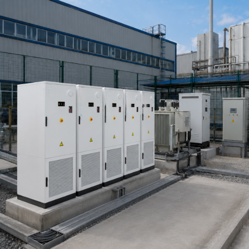
A PCS has no combustion engine and no oil, but it is not maintenance-free. Its wear items are capacitors, fans, and filters, and its risks are dust, heat, and firmware drift. A realistic service plan:
- Monthly: Check alarm logs, verify cooling fans and airflow, inspect air filters (clean or replace in dusty environments).
- Annually: Torque-check power connections, clean heat sinks, test protection trips, and review firmware against the vendor’s current release. Capacitor health checks matter from year five onward.
- Every 5-10 years: Budget for fan replacement and DC-link capacitor service, the two components that age fastest.
Design life is typically 15-20 years for the power stage, longer than the battery it serves. Plan on one PCS outliving two battery augmentations, and keep firmware and protection settings under change control so a settings update never silently erases the protection coordination you paid to engineer. A standby power system only stays reliable when every layer of it gets this kind of scheduled attention.
Frequently Asked Questions
Is a PCS the same as an inverter?
No. A standard inverter converts DC to AC in one direction. A PCS is bidirectional, charging and discharging, and adds grid-support functions like four-quadrant reactive power, frequency response, and millisecond control.
How do you size a PCS for battery storage?
Divide usable battery energy by discharge hours to get base power, divide again by efficiency (about 0.96), then multiply by a 1.1 safety factor. A 4,000 kWh, 2-hour system needs roughly 2,300-2,500 kW of PCS.
What is the difference between grid-forming and grid-following PCS?
Grid-following units lock onto an existing grid and inject current; grid-forming units create the voltage and frequency reference themselves. Weak grids, islanded operation, and black start require grid-forming.
What efficiency should a PCS have?
97-98.5% at rated load is the current norm. Check the part-load efficiency curve too, since storage systems spend much of their time at 25-50% of rated power.
What certifications does a PCS need?
IEC 62477 for converter safety internationally, IEEE 1547 and UL 1741 for North American grid interconnection, plus whatever local grid code applies at the point of connection.
How long does a PCS last?
The power stage typically lasts 15-20 years with scheduled maintenance. Fans and DC-link capacitors need service around years 5-10. A PCS will usually outlive the first battery pack it serves.
Can a PCS run a site without any grid connection?
Yes, but only in grid-forming mode paired with a local source such as a diesel genset or enough battery capacity to carry the load. A grid-following PCS has nothing to follow when the grid is absent and will simply trip offline.
What is the difference between AC-coupled and DC-coupled storage?
AC-coupled storage connects the battery through its own PCS onto the AC bus, which suits retrofits and diesel hybrids. DC-coupled storage shares a hybrid inverter with solar on the DC side, which saves one conversion stage but only makes sense in new solar-plus-storage builds.
Conclusion
A power conversion system for energy storage determines how much of your battery investment actually reaches the bus. Spec it as carefully as the battery itself: choose the architecture for your availability needs, choose grid-forming for weak grids and islanded duty, and size from usable energy with efficiency and safety margins built in. If the project pairs storage with diesel, decide early who forms the grid, because that answer drives the whole control design.
At Shandong Huali Electromechanical Co., Ltd., we design hybrid power systems that combine Huali diesel generator sets from 8kVA to 4000kVA with battery storage for mining, industrial, and off-grid sites worldwide. Our warranty and after-sales support program covers system sizing, commissioning, and long-term technical support across 20+ countries.
If you are evaluating a hybrid genset-plus-storage plant, or want a second opinion on a PCS specification, contact our engineering team today. For the broader picture, see our guide to industrial power solutions.
