
A generator foundation design has to do two jobs at once: carry the set’s dead weight without the soil settling under it, and absorb the dynamic forces the engine throws into the ground every revolution. Get the first right and ignore the second, and you will be re-grouting anchor bolts within a year. Get both wrong and you will be pouring a second pad.
Most published guidance treats a generator foundation as a weight problem. A 1,000 kVA set does weigh around 10 tonnes, so weight matters. But the reason genset pads crack, drift, and loosen is almost never the static load. It is vibration, and it is soil that nobody tested.
This guide covers the numbers that drive a generator foundation design: allowable bearing capacity by soil type, the formula for sizing pad area, concrete and rebar specifications, and how to decide between a rigid pad and an isolated one. Where a value depends on your specific site or machine, we say so instead of guessing.
Key Takeaways
- Size the pad from allowable bearing pressure, not from a catalog: required area = set weight ÷ (allowable soil pressure − concrete self-weight per m²). A thicker pad needs a larger footprint, not a smaller one.
- Concrete density is a fixed 2,400 kg/m³ (150 lb/ft³). That constant is what turns a required foundation mass into a real volume and thickness.
- Bearing capacity spans roughly 25 kN/m² for soft clay to 600 kN/m² for dense sand and gravel. That single variable can change your pad area by a factor of twenty, which is why a geotechnical report is cheaper than a repour.
- Published supplier installation guidance commonly requires the supporting structure to carry 125% of the set’s wet weight where no vibration isolators are fitted.
- A generator foundation is a machine foundation. Rigid pads work up to roughly 500 kVA; above that, dynamic analysis and often an inertia block decide the design.
What a Generator Foundation Design Has to Do
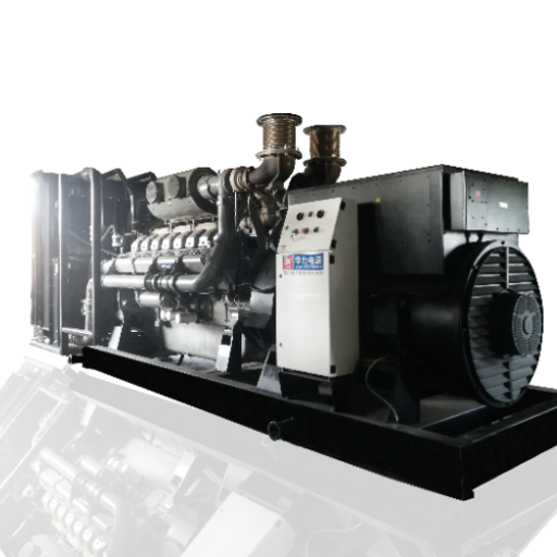
A generator foundation is the structural element that transfers a generating set’s static and dynamic loads into the ground while holding the engine and alternator in permanent alignment.
Alignment is the real deliverable. A genset’s engine and alternator are coupled on a common shaft. If the foundation lets one end settle even a few millimetres relative to the other, the coupling misaligns. The bearings and coupling elements then wear at a rate no maintenance schedule can keep up with. For how the foundation sits inside the wider installation, see stationary generator sets: the complete guide.
Static load versus dynamic load
Static load is everything that just sits there: engine, alternator, skid base, radiator, exhaust, oil, coolant, and full fuel in the day tank. This is the number you divide by bearing pressure to get pad area, so it pays to total it properly: see how to make a generator load schedule.
Dynamic load is what the engine does to the foundation while running. A diesel engine produces torque pulses at firing frequency, pushing down, up, and sideways several times per second. Dynamic load scales with the set’s mass and running speed, and it reaches the foundation through the mounting points rather than spread evenly across the skid.
This is why a pad designed purely on weight can fail. The static calculation can look comfortable while the dynamic load at a single mounting foot exceeds what the concrete beneath it can take.
Why this is a machine foundation, not a building foundation
Building foundations are designed so nothing moves, ever. Machine foundations are designed so the movement happens at a frequency the structure does not amplify. Every foundation has a natural frequency, and the engine produces forcing frequencies at its running speed and multiples of it. If the two land close together the foundation resonates and amplitude climbs sharply.
Soil Bearing Capacity: The Number That Drives Everything
Allowable bearing capacity is the pressure a soil can carry without failing or settling excessively. It is expressed in kN/m² or kPa, and it is the single most consequential input in a generator foundation design.
Typical indicative values:
| Soil type | Indicative allowable bearing capacity | What it means for a genset pad |
|---|---|---|
| Massive bedrock | 600–1,000+ kN/m² | Rarely governs. Anchor directly into rock if permitted. |
| Dense sand and gravel | 200–600 kN/m² | Excellent. A modest pad handles most industrial sets. |
| Compacted fill, hard clay | 100–200 kN/m² | Workable. Confirm compaction testing. |
| Medium dense sand | 100–300 kN/m² | Workable. Watch for groundwater. |
| Stiff clay | 75–150 kN/m² | Expect settlement. Consider a mat. |
| Loose sand, soft clay | 25–75 kN/m² | Usually requires a mat, piles, or ground improvement. |
These are indicative ranges for preliminary thinking, not design values. A geotechnical report governs. The gap between the top and bottom of that table is a factor of twenty or more in pad area. No amount of careful concrete work compensates for a foundation bearing on soft clay.
Reading a geotechnical report
You are looking for three numbers, not thirty pages: allowable bearing capacity at your proposed founding depth, expected total settlement, and the depth to groundwater. Differential settlement matters more than capacity on clay: a pad that stays intact while sinking 25 mm at one corner has still misaligned your coupling.
If the report gives capacity at a depth shallower than your required founding depth, ask for it recalculated at design depth. Capacity rises with depth, and the difference can remove the need for a mat.
Generator Foundation Design: Sizing Area, Thickness, and Reinforcement
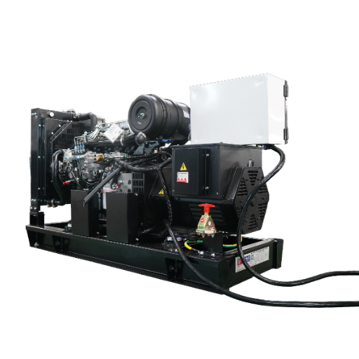
Here is the formula that does the work in any diesel generator foundation design. Ignore the catalog tables until you have run it.
Required pad area:
A = W_set / (q_allowable − (ρ_concrete × h))Where A is pad plan area in m², W_set is the set’s total wet weight in kN, q_allowable is allowable bearing capacity in kN/m², ρ_concrete is 2,400 kg/m³ (23.5 kN/m³), and h is pad thickness in metres.
The denominator term matters. A thicker pad adds weight the soil must also carry, so increasing thickness without increasing area reduces your margin. Most people assume the opposite.
A pad that got thicker instead of wider. A contractor in Lagos had a 500 kVA set and a geotechnical report allowing 90 kN/m². He sized the pad on the set’s weight, then doubled the thickness for what he called extra strength. The extra concrete added load the soil also had to carry, and the revised calculation no longer closed. The pad settled 30 mm at one corner within six months, and the replacement footprint came out half again as large. Thickness was never the problem.
Ground pressure check:
P = W / AWhere W is the total load and A is the area actually transferring it: the footprint of the skid rails or vibration mounts, not the pad’s full plan area. This number must stay below the concrete’s capacity directly beneath the mounting points.
A worked example
Take a 1,000 kVA diesel set. For planning, assume a wet weight of around 10,000 kg, which is 98 kN. Assume a chosen pad thickness of 0.6 m, which gives a concrete self-weight of 0.6 × 23.5 = 14.1 kN/m².
| Allowable bearing capacity | Net capacity available for the set | Required pad area |
|---|---|---|
| 150 kN/m² (good ground) | 150 − 14.1 = 135.9 kN/m² | 98 ÷ 135.9 = 0.72 m² |
| 75 kN/m² (stiff clay) | 75 − 14.1 = 60.9 kN/m² | 98 ÷ 60.9 = 1.61 m² |
| 30 kN/m² (soft clay) | 30 − 14.1 = 15.9 kN/m² | 98 ÷ 15.9 = 6.16 m² |
Same machine. The required area varies by a factor of nearly nine across that table, and at 30 kN/m² you are no longer building a pad in any practical sense. That is the moment to call a geotechnical engineer rather than a concrete supplier.
⚠️ The 10,000 kg figure is an indicative planning weight, not a specification. Confirm your set’s wet weight from its datasheet, including oil, coolant, and full fuel. Wet weights for a given kVA rating vary between manufacturers and configurations.
Thickness and foundation mass
For reciprocating machinery, a long-standing rule of thumb is that the foundation should weigh 2 to 3 times the mass of the machine it supports. Use the higher end where vibration is severe or the set runs continuously. With concrete’s fixed 2,400 kg/m³ density, that converts a required mass into a required volume.
The rule does not set thickness independently of area. You choose thickness for stiffness and cover, then size area for bearing. Where the two disagree, bearing governs, and you add mass by increasing thickness and area together.
Reinforcement and concrete specification
Specify concrete at a minimum of 20 MPa (3,000 psi) for genset pads, and 25–30 MPa where the set runs continuously. A typical slump is around 100 mm (4 in), which keeps the mix workable without segregating. Slump and strength are specified together; a wet mix placed for convenience is a weaker pad.
Reinforcement for a pad is usually deformed bar in a bottom mat, placed with adequate cover to the soil face to prevent corrosion. Spacing follows from the span between support points rather than a fixed rule, so this is where your structural engineer earns their fee. Extend reinforcement across the full pad and provide edge reinforcement. Pads fail at the edge far more often than at the centre.
Anchor Bolt Design, Grout, and Proof Load
Cast-in-place anchor bolts set in a template before the pour give the best alignment. Post-installed anchors are acceptable but must be designed for the dynamic load case, not just the static one, using recognised anchorage design provisions rather than a catalogue pull-out figure.
Grout the gap between the skid base and the pad fully, with non-shrink high-strength grout. Partial grouting leaves the skid bearing on a few high points, which concentrates load and defeats the point of the pad.
Once the set is down and grouted, acceptance testing and load bank testing are what prove the foundation and the set behave under real load rather than only on paper.
Vibration Isolation: Getting the Frequency Right

Vibration isolation is the part of a generator foundation design that most projects skip, and it is the part that determines whether the pad is still serviceable in five years.
The two approaches
Rigid mounting. The foundation is made heavy and stiff enough that its natural frequency sits well above the engine’s forcing frequencies. Simple, durable, and cost-effective up to roughly 500 kVA. Beyond that, getting a high enough natural frequency out of a practical pad becomes expensive.
Isolated mounting. Resilient mounts between the skid and the foundation deliberately lower the system’s natural frequency below the lowest forcing frequency, decoupling the set from the structure. It is the usual choice for larger sets, for rooftop and upper-floor installations, and wherever the foundation is shared with occupied space.
Published load guidance
Where no isolators are used, published supplier installation guidance commonly requires the supporting structure to carry 125% of the set’s wet weight. That margin covers dynamic amplification at the mounting points, and it is a useful sanity check even when isolators are fitted.
Inertia blocks
For large sets, or any installation with a strict vibration limit, the foundation becomes an inertia block: a concrete mass, often 2 to 3 times the set’s, on resilient isolation. Its job is to absorb the engine’s oscillating forces rather than pass them into the building.
Blocks are built with a gap around the perimeter and no rigid connection to the surrounding floor, so the block moves as a unit. A block poured tight against a wall transfers vibration straight into it and achieves nothing.
When vibration stops being theoretical
Liu Wei, a commissioning engineer at Huali, was called to a textile plant in Jiangsu. A 1,250 kVA set had been running eleven months on a foundation designed for weight alone, with no isolation. Floor staff had complained about vibration for months. On inspection, four of the eight anchor bolts showed grout cracking and fretting at the base.
The plant had not lost a generator. It had lost tolerance in precision spinning equipment sharing the same slab. Retrofitting resilient mounts and regrouting cost less than the operator feared, but the set was offline for two days. A vibration check at design stage would have surfaced the problem for free.Two days without backup is easier to accept when another set can carry the load. Our guide to N+1 generator redundancy explains how one extra unit keeps a site covered while a set is down for regrouting, mount replacement, or foundation repair.
Site Preparation, Drainage, and Codes
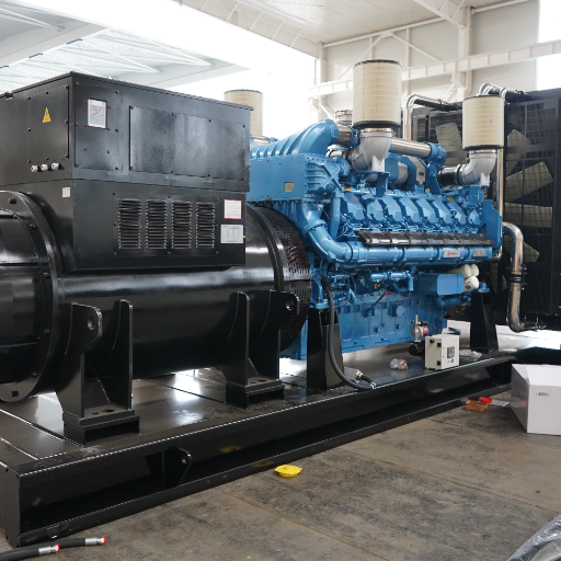
Sub-base and compaction
Excavate to design depth, place a compacted granular sub-base, and test compaction before the pour. Concrete poured onto loose or organic material settles unevenly no matter how good the concrete is. Strip all topsoil from beneath the footprint.
Drainage and containment
Finish the pad so water runs off rather than pooling under the set, and keep the pad top 100–150 mm above surrounding ground level. For sets with integral or adjacent fuel storage, check whether local rules require secondary containment, and design a bunded slab if so. Our guide to diesel fuel storage regulations covers containment by jurisdiction.
Frost depth
Where ground freezes, the footing must extend below the local frost line or be insulated. Frost heave lifts pads unevenly and seasonally, which is far harder to diagnose than a one-time settlement. Frost depth varies enormously by region, so use your local building code value rather than a rule of thumb. Related siting constraints are in our guide to generator clearance requirements.
Codes and standards
| Standard | What it covers for a generator foundation |
|---|---|
| NFPA 37 | Installation and use of stationary combustion engines, including siting and support |
| NFPA 110 | Emergency and standby power systems, including installation requirements that the foundation serves |
| ACI 351.3R | Foundations for dynamic equipment, the reference for machine foundation analysis |
| National building code (local) | Frost depth, seismic design, and structural design provisions |
Structural design of the foundation itself is governed by your local building code; NFPA and ACI add the machine-specific requirements on top. Confirm the edition adopted in your jurisdiction, since these standards are revised on multi-year cycles.
Frequently Asked Questions
How thick should a generator foundation be?
There is no single thickness that works. Thickness is set by the foundation mass you need for stiffness, by cover around reinforcement, and by the loads at the mounting points. You choose thickness, then size plan area from allowable bearing capacity. For reciprocating machinery a common starting rule is a foundation mass of 2 to 3 times the set’s mass, converted to volume at concrete’s 2,400 kg/m³.
How do I calculate generator pad size for a concrete slab?
Divide the set’s total wet weight by the net allowable bearing capacity, where net capacity is soil capacity minus the concrete’s own self-weight per square metre. A 10,000 kg set on ground rated at 150 kN/m² needs about 0.72 m² of pad at 0.6 m thick; the same set on stiff clay at 75 kN/m² needs about 1.61 m².
Does a generator need a concrete pad?
Not always. Small portable sets can run on a compacted gravel base or a proprietary composite pad. Any permanently installed industrial set should be on a designed foundation, because the foundation is what maintains engine-to-alternator alignment and controls vibration. Precast pads sold for home standby units are sized for sets in the 8–26 kW range and are not appropriate for industrial gensets.
What soil bearing capacity does a generator foundation need?
There is no universal threshold, because the required capacity depends on the set’s weight and the pad area you are willing to build. Practically, above about 100 kN/m² a straightforward pad works; between 50 and 100 kN/m² expect a mat or a larger footprint; below 50 kN/m² you are usually looking at ground improvement or piles. Get a geotechnical report before deciding.
Do I need vibration isolation, or is an inertia block enough?
Isolation becomes the deciding factor above roughly 500 kVA, where the foundation shares a structure with occupied space, on upper floors and roofs, and wherever nearby equipment has tight vibration tolerances. An inertia block is the usual way to get there. It is a mass of 2 to 3 times the set, on resilient isolation, with a free gap around its perimeter so it can move as a unit.
Conclusion
A generator foundation design comes down to four numbers: the set’s wet weight, the allowable bearing capacity of your soil, concrete’s fixed density of 2,400 kg/m³, and the engine’s forcing frequency. Measure all four before you pour. The area formula and the ground pressure check size the pad; the frequency check decides whether it needs isolation.
The most expensive mistake here is not a thin pad. It is a comfortable static calculation that never asks what the soil is, and never asks what the engine does to the concrete it is bolted to. Against the total cost of a standby power installation, a geotechnical report and a properly designed foundation are a small line item, as our breakdown of stationary generator cost sets out.
If you are specifying a foundation for an industrial set, we will give you the inputs. Our engineering team supplies wet weight, mounting footprint, dynamic load data, and anchor bolt layouts for every generator we build, from 8 kVA to 4,000 kVA. Your structural engineer is then designing against real numbers. Send us your set specification and we will return the foundation data →
