
Generator no voltage, or a generator not producing power, almost always means the alternator is not being excited, the output circuit is open, or the meter is wrong. Check the main breaker, the transfer switch, and the actual terminal voltage first, then work inward through the AVR, exciter, rotating diodes, and residual magnetism.
At 4:10 a.m., Marta, a cold-storage maintenance supervisor, started a 400 kVA standby set after an outage. The engine settled at 1,500 rpm. The panel showed 0 V.
She had ordered an AVR when a technician measured 398 V phase to phase at the alternator terminals. A failed sensing fuse had disabled the panel voltmeter.
You are right to suspect the alternator when the engine runs and the lights stay off. But the order of checks matters. This guide shows how to confirm the fault, separate the five causes, test excitation safely, and decide when field flashing helps.
We build and test diesel generator sets (gensets) from 8 kVA to 4,000 kVA. If the set is down, send the nameplate, controller model, and phase readings to our engineers. For the wider picture, see common generator problems.
Key Takeaways
– Generator no voltage is usually an output or excitation fault, not a failed engine.
– Measure at the terminals; a failed panel voltmeter can mimic a total failure.
– Low voltage with low frequency means speed; low voltage at normal frequency means excitation.
– Residual magnetism only matters on self-excited sets. PMG sets do not need flashing.
– Field flashing is model-specific; the wrong terminal or polarity can destroy the AVR.
What Does Generator No Voltage Mean?
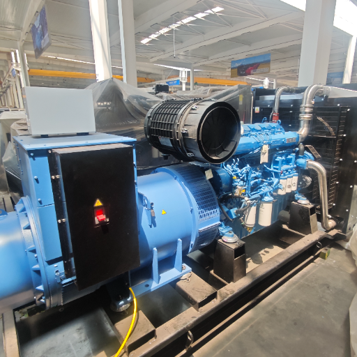
Generator no voltage means the terminals show zero or near-zero voltage while the engine runs at rated speed. A true zero is less common than a very low reading. Residual voltage is typically 10% to 20% of rated output, according to Stamford / AvK AGN-173. On a high-voltage alternator, about 2 kV can remain.
Treat the output as live until you prove it dead.
The reading depends on where you take it. A controller display, a panel voltmeter, and a terminal meter are three different measurements. A failed fuse or meter can show zero while the terminals are live, and an open breaker can show zero at the load.
A generator set has three circuits that must work together:
- Measurement: voltmeter, controller sensing, and potential transformers.
- Output: main breaker, cable, transfer switch, and reconnect links.
- Excitation: AVR, sensing supply, exciter, rectifier, rotor, and stator.
A fault in any circuit can look like no voltage. Find which circuit is open. The generator control panel gives the first evidence, not the final number.
First 10 Minutes: Confirm the Fault Safely
Work in this order. Stop before any step that requires live work you are not qualified and equipped to perform.
- Isolate and lock out. Open the generator breaker and transfer switch, apply lockout/tagout, and prove the terminals dead. Follow NFPA 70E for PPE and arc-flash boundaries, and wait for stored charge.
- Read the controller first. Record the alarm, event log, last stop code, frequency, and voltage on every phase. A low-voltage alarm may be a sensing problem.
- Measure at the alternator terminals. Record L1-L2, L2-L3, L1-L3, and each line-to-neutral voltage. Compare with the nameplate and a second meter.
- Check the output path. Inspect the main breaker, transfer switch, cable terminations, and reconnect links. Confirm the transfer switch actually transferred and the contactor closed. A link in the wrong position can give a low reading.
- Check frequency. A four-pole set at 1,500 rpm should produce 50 Hz; at 1,800 rpm, 60 Hz. Low frequency points to the engine or governor, not the AVR.
- Do not reset repeatedly or bypass protection. The cause can be a short circuit or winding fault. Repeated closing puts the alternator and the operator at risk.
If the terminals show normal voltage but the load side does not, the fault is in the output path. If the terminals show zero or residual voltage, continue below.
The Five Causes of Generator No Voltage
Most no-voltage faults fall into five groups. The table gives the first check for each.
| Cause | What you see | First check | Usual repair |
|—|—|—|—|
| Open output circuit | Normal at terminals, zero at load; one phase low | Main breaker, transfer switch, cable, links | Repair breaker or connection |
| AVR or sensing fault | Zero or low at normal frequency; AVR alarm | Sensing fuse, wires, AVR supply | Restore sensing or replace AVR |
| Exciter or rectifier fault | Builds then collapses; low or unbalanced | Field voltage, diodes, varistor | Replace diode or varistor; repair exciter |
| Loss of residual magnetism | Near-zero on a self-excited set; may build with a flash | Confirm excitation type; measure residual | Flash per manual; find cause |
| Stator, rotor, or PMG fault | One phase low, imbalance, burning smell | Winding and insulation resistance, PMG output | Rewind or replace |
Open Output Circuit
The alternator can be healthy and still deliver nothing. The main breaker may be open, the transfer switch may be stuck in utility, a cable lug may be loose, or a reconnect link may be on the wrong terminal.
Rule this out first. Measure at the terminals, the load side of the breaker, and the transfer switch. The point where voltage disappears is the fault.
A loose connection can also hold voltage at no load and collapse under load. Inspect for discoloration and heat damage, and torque terminals to the manufacturer’s value.
AVR or Sensing Fault
The automatic voltage regulator (AVR) controls exciter field current. It needs a voltage signal from the output and a power supply from the main stator or a permanent magnet generator (PMG).
A blown sensing fuse, broken wire, loose terminal, or failed sensing transformer can make the AVR think the output is wrong. The result may be zero, high, or unstable output. A panel reading of zero doesn’t prove the alternator is dead.
Check the sensing fuses and terminals, then the AVR supply. A failed PMG can look like a failed AVR.
Exciter and Rotating Rectifier Fault
A brushless alternator excites in stages. The AVR applies DC to the exciter stator. The exciter rotor produces AC, and the rotating rectifier converts it to DC for the main rotor, which induces voltage in the stator. A varistor protects the diodes from spikes.
A shorted diode or varistor can stop voltage build-up. An open diode may allow build-up at no load, then lose voltage under load. A damaged exciter winding has the same effect.
Start with the AVR output and field voltage. Field voltage with zero output means the fault is downstream. A technician can test the diodes and varistor with the set stopped.
Loss of Residual Magnetism
A self-excited alternator uses the small magnetic field left in the exciter stator to start voltage build-up. It can be lost after long storage, mechanical shock, vibration, a run-down with load connected, a wrong-polarity flash, or an exciter rewind.
A set that sat for a year may start easily and show only a few volts. The engine, fuel, and AVR can all be fine.
This doesn’t apply to PMG-excited alternators. A PMG powers its own AVR, so find the PMG or AVR fault instead.
For any winding fault, stop and call a qualified service team. The generator winding guide explains the repair options.
Stator, Rotor, and PMG Fault
Winding faults are less common but more serious. A shorted turn, open phase, or insulation failure can produce zero, low, or unbalanced voltage. A burning smell, discoloration, or a breaker that trips immediately are warning signs.
A PMG fault is a separate case. The PMG stator, rotor, or insulation can fail, removing AVR power and looking like a failed AVR. Test the PMG output at its leads before replacing the AVR.
For any winding fault, stop and call a qualified service team. The generator winding guide explains how insulation, harmonics, and rewinds affect the repair decision.
Generator No Voltage vs Low Voltage: Read the Clues
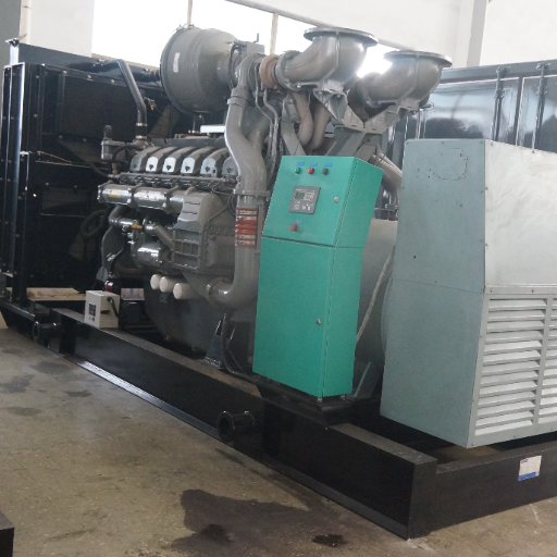
The voltage reading alone is not enough. Frequency and phase balance tell you where to look next.
| Reading | Most likely area | Next check |
|---|---|---|
| 0 V on all phases, normal frequency | Excitation or open output | Breaker, terminals, AVR output |
| Low voltage and low frequency | Engine speed or governor | Tachometer, fuel supply, governor |
| Low voltage at normal frequency | Excitation or AVR | Sensing, AVR supply, field voltage |
| One phase low or zero | Open circuit or stator fault | Links, breaker, winding resistance |
| Normal at no load, collapses under load | Diode, AVR, undersized set, or cable drop | Diode test, load current, cable drop |
Voltage is roughly proportional to speed at constant excitation. If frequency is also low, correct the engine speed first. If frequency is normal and voltage is low, the excitation system is the problem.
Phase balance is the other clue. A large difference points to an open circuit, a loose link, or a stator fault.
Consider Amina, a hospital facilities engineer who replaced a feeder cable on a 750 kVA set. After reconnection, L1-L2 read 400 V and L2-L3 read 399 V, but L1-L3 read 118 V. The alternator was fine.
One reconnect link was not tightened. The phase reading sent the technician to the link box instead of the stator.
If the set holds voltage at no load but sags under load, that is voltage drop under load, not no voltage. A dip when a motor starts is also separate; see voltage dip when a motor starts. Don’t turn up the AVR to hide either one.
How to Test the AVR and Excitation System
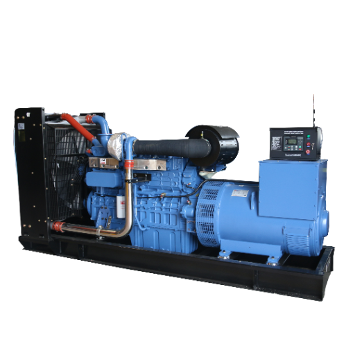
This is test logic, not a live-work procedure. Testing inside a terminal box requires a qualified person, the correct meter category, PPE, and lockout/tagout.
- Verify the sensing input. Compare the AVR sensing voltage with the terminal voltage and nameplate, and check all phases and fuses.
- Verify the AVR power supply. Confirm the main stator or PMG supply. A PMG should be balanced at its leads; the manual gives the range.
- Measure exciter field voltage. At F+ to F-, compare with the AVR or alternator manual. Field voltage present with zero output means the fault is downstream.
- Run a separate-excitation test. Isolate the AVR, apply controlled DC to the exciter field, and run at rated speed. Full balanced voltage means the alternator and rectifier are healthy and the AVR or sensing circuit is at fault. Low balanced voltage points to the exciter or diodes. Unbalanced voltage points to the stator.
- Test the diodes and varistor. With the set stopped, check each diode both ways and the varistor for a short or open. Replace a failed varistor and follow the manual on replacing all diodes.
- Test insulation resistance only with the AVR disconnected. A megger can destroy semiconductors. Follow the manual for test voltage, minimum resistance, and discharge time.
Warning: Never use a megger with the AVR connected. Isolate it, test at the manual’s voltage, and ground the winding afterward to remove stored charge.
Full voltage under separate excitation means a healthy power circuit; the problem is control. Residual voltage only means a power-circuit fault. One low phase means a stator or connection fault. If the readings do not fit, send them to our engineers.
Field Flashing: When It Works and When It Doesn’t
Field flashing is a brief DC pulse to the exciter field, used to restore residual magnetism or correct polarity. It applies only to self-excited alternators, and only when the manual calls for it.
Two real procedures show why the manual matters:
| Example | Set state | DC source | Terminals | Duration | Success check |
|---|---|---|---|---|---|
| Basler AVC63-4 | Prime mover at rest | Ungrounded source, 12 V DC or less, through a 3 to 5 ohm resistor | F+ and F- | About 3 seconds | Terminals 3 and 4 disconnected; start; more than 6 Vac means build-up |
| Stamford self-excited alternator | Rated speed, no load | 12 V battery with a diode in one lead | X+ (F1) and XX- (F2) | Maximum 1 second | Voltage builds; wrong polarity can destroy the AVR |
The Basler procedure is in the AVC63-4 manual. The Stamford procedure is in the alternator service manual. They differ in set state, duration, and connection point.
Dev, a plant engineer, learned this with a 500 kVA set that had sat for 14 months. The engine ran, the panel showed 8 V, and two replacement AVRs changed nothing. The exciter had lost residual magnetism; a brief flash per the manual restored voltage. The two AVRs were unnecessary.
Use these rules:
- Never flash the AVR terminals or sensing leads. Apply DC only to the field terminals named in the manual.
- Check polarity before you connect. Reversed polarity can reverse residual magnetism and damage the AVR.
- If voltage builds and then collapses when the DC source is removed, flashing is not the fix. The fault is in the AVR, the diodes, or the winding.
- Do not use the drill method or apply battery voltage to the output. Both can damage the alternator or injure the operator.
- Do not assume flashing will fix a PMG set. It does not depend on residual magnetism.
Prevention and When to Stop
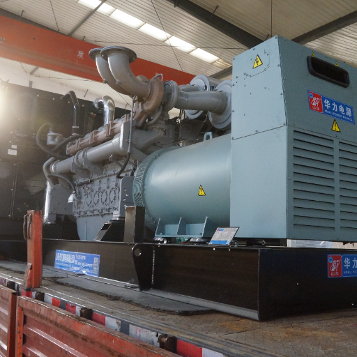
No-voltage faults are easier to prevent than to diagnose. The most useful habits are simple:
- Exercise the set under load every month, not just at idle. A no-load run does not prove the alternator can carry current.
- Keep anti-condensation heaters energized when the set is stopped. Moisture lowers insulation resistance and can cause a flashover.
- Inspect and torque output terminals annually.
- Record insulation resistance at commissioning and at each major service. A falling trend matters more than a single reading.
- Keep a spare AVR, diode set, and varistor matched to the alternator. A wrong spare is worse than no spare.
- Load-bank test after a repair, a long storage period, or a major cable change.
- Use the generator maintenance planner and the commissioning checklist to keep the schedule and baseline records.
Stop and call an engineer if you see any of the following:
- A burning smell, smoke, or discoloration in the terminal box or alternator.
- A cracked or burnt varistor, or a diode that fails in both directions.
- Insulation resistance below the alternator manual’s minimum.
- A large phase imbalance that remains after tightening the links.
- A fuse or breaker that trips again immediately after reset.
- Residual voltage high enough to be dangerous on a high-voltage set.
- No nameplate, manual, or wiring diagram to identify the equipment.
Do not bypass protection, repeatedly reset a breaker, or flash a set you cannot identify. A service call costs less than a rewound alternator or an arc-flash injury.
FAQ
Why is my generator running but not producing voltage?
A generator runs but no power reaches the load because the engine and alternator are separate systems. A running engine only proves that fuel, compression, and speed are available. No voltage usually means an open output breaker, lost AVR sensing or supply, failed exciter or diodes, or lost residual magnetism.
What causes low voltage on a generator?
Low voltage at normal frequency usually points to the AVR, its sensing circuit, or the exciter. Low voltage with low frequency points to engine speed. Low voltage only under load can come from a diode fault, an undersized set, or cable drop. Check frequency and phase balance before adjusting the AVR.
How do you regain residual magnetism in a generator?
On a self-excited alternator, apply DC to the exciter field exactly as the manufacturer’s procedure specifies. The voltage, resistor, polarity, duration, and connection point vary by model. A PMG-excited alternator does not rely on residual magnetism, so flashing will not help.
Can you remagnetize a generator yourself?
Only if you have the model-specific procedure, the correct DC source, a meter, and the training to work safely. A wrong connection can destroy the AVR or reverse the field. For an industrial set, this is a technician task, not a DIY repair.
What is field flashing, and can I do it myself?
Field flashing is a brief DC pulse to the exciter field to restore residual magnetism. It is model-specific. The Basler AVC63-4 example uses an ungrounded source of 12 V DC or less through a 3 to 5 ohm resistor for about 3 seconds at rest. The Stamford example uses a 12 V battery with a diode for no more than 1 second at rated speed.
Conclusion
Generator no voltage is a circuit problem, not automatically an alternator problem. Check the measurement, output, and excitation circuits in that order, then use frequency and phase balance.
The five causes are an open output circuit, an AVR or sensing fault, an exciter or rectifier fault, lost residual magnetism, and a stator, rotor, or PMG fault. Field flashing addresses only the fourth, and only on a self-excited set.
If the set is down, contact our engineering team with the nameplate, controller model, and phase readings. We build and test sets from 8 kVA to 4,000 kVA.
